Controlling a robot’s direction, speed, individual wheel movement, and more via a single FPC wire makes the overall design compact and efficient. The system can also be configured for Wi-Fi, hand gestures, or other control methods. However, building a robot usually involves separate motor driver modules, displays, batteries, controllers, and external wiring, making the setup bulky and time consuming. This becomes even more difficult when designing a miniaturized robot.
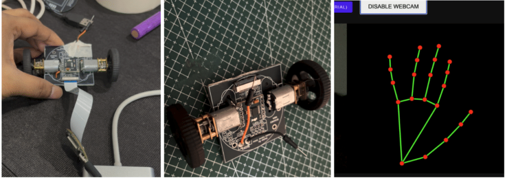
To solve this, I designed an AI Hand Gesture Controlled Mini Robot PCB Using MediaPipe and DRV8833, which also acts as a self-sustaining chassis for the robot. The motors, driver module, battery, power system, display, and additional servo motor slots can all be mounted directly on the PCB. Everything can be assembled using SMD components on the PCB itself, removing complex and messy wiring while keeping the complete robot design extremely compact at only 4 cm. The PCB also provides FPC and header connections to interface with the MCU and control the robot.
If you are using the IndusBoard coin, you can directly connect it to the robot and program it however you want to use and control the robot. Most of the work is only done with one FPC connection. Refer to Figure 1.
If you are using any other MCU, you only need to connect four signal wires, and you can design your own FPC adapter to directly interface the MCU with the robot, making the system simple and flexible for everyone.
Bill of Materials
Table 1. Robot PCB Parts
| ID | Name | Designator | Footprint | Quantity |
| 5 | Screw Terminal | CONN1 | SCREW_TERMINAL_2PIN | 1 |
| 6 | XW0520012-240R-001 | FPC2 | FPC-SMD_24P-P0.50_XW0520012-240R-001 | 1 |
| 7 | 4 PIN HEADER VGT | H1,H2,H5 | HEADER 3 PIN VGT | 3 |
| 8 | 3 PIN HEADER VGT | H3,H4 | HEADDER 3 PIN VGT | 2 |
| 9 | N20_DC_Motor | M1 | N20_DC_MOTOR | 1 |
| 10 | N20_DC_Motor | M2 | N20_DC_MOTOR | 1 |
| 11 | DRV8833 Module | U2 | DRV8833 DUAL MOTOR DRIVER MODULE | 1 |
Table 2. Motor Driver Module Parts
| ID | Name | Designator | Footprint | Quantity |
| 1 | 10uF | C7 | C0805 | 1 |
| 2 | 10nF | C9 | C0805 | 1 |
| 3 | 2.2uF | C10 | C0805 | 1 |
| 4 | DRV8833PW | U5 | HTSSOP-16_L5.0-W4.4-P0.65-LS6.4-TL-EP-1 | 1 |
Gesture Controlled Mini Robot Circuit
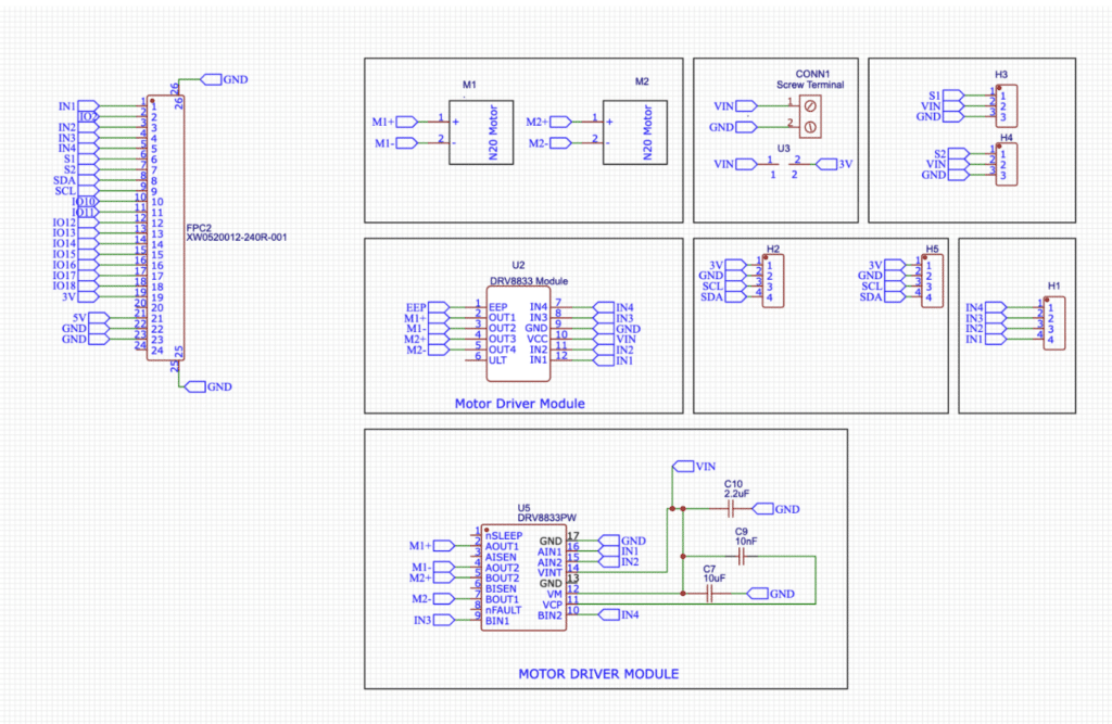
Here in the design, you can either use the pre-made DRV8833 motor driver module and directly integrate its footprint into a small, compact PCB, or you can design your own custom DRV8833 motor driver circuit using SMD components and integrate it directly onto the PCB. Both options are provided in the design. The schematic includes the footprint for the ready-made DRV8833 module as well as a custom DRV8833 SMD motor driver circuit with the same pinout, allowing either option to be used on the robot PCB.
The circuit uses two N20 DC motors connected through the DRV8833 dual motor driver. The motor outputs are routed to the bottom PCB layer with SMD solder pads so that the N20 motors can be soldered directly onto the PCB easily, reducing wiring and making the robot compact and reliable. The DRV8833 driver receives control signals IN1, IN2, IN3, and IN4 from the controller board to control the direction and speed of both motors independently.
Additionally, two I2C connector slots are provided in the design. These connectors can be used for adding an OLED display, LCD display, or any other I2C-based sensors such as IMU, accelerometer, magnetometer, or environmental sensors. Two servo motor headers are also included with VIN and GND power connections, allowing servo motors to be connected directly to the PCB without external wiring.
The overall design provides flexibility for connecting extra sensors, motors, servo motors, and displays directly onto the main robot PCB. This makes the system modular, compact, and easy to assemble without complex external wiring. Fig. 2 shows the complete circuit diagram of the robot. If you want to design a fully custom motor driver instead of using the ready made DRV8833 module, the complete footprint and SMD circuit for the custom DRV8833 motor driver are also provided in the motor driver section of the schematic.
PCB Design
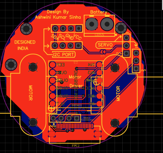
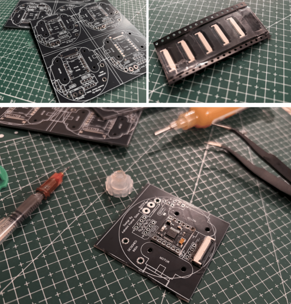
Next, we design the PCB. We will keep the motor driver module on top, and the N20 wires are routed through to the bottom layer. We will also provide mounting holes for the N20 motor bracket.
SMD Work
Now, after designing the PCB, we get it manufactured. Then, we mount the motor on the PCB and perform SMD soldering on the solder pads for the motor pins on both sides. Next, we SMD solder the motor driver on the PCB along with its other discrete components, connectors, and capacitors. Lastly, we perform the FPC SMD soldering.
Programming AI based Hand Gesture Controlled Mini Robot
Now we move to the coding part, where the robot is programmed to detect hand gestures and control the robot through a USB serial connection. In this project, MediaPipe is used along with JavaScript to create a web application. The web application uses WebSerial to communicate with the board over USB and control the robot in real time based on detected hand gestures.
Serial Command Code
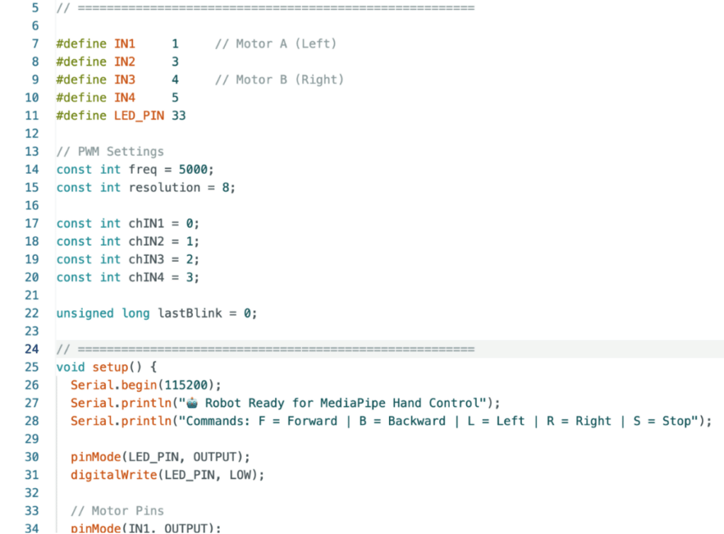
First, the serial communication code is written for the IndusBoard Coin or any other MCU board connected to the robot through the FPC connector or motor input pins. The board continuously receives data from the serial port and controls the motors accordingly, allowing the robot to move left, right, forward, or backward, based on the commands sent from the web application.
Ai Media pipe Webapp code
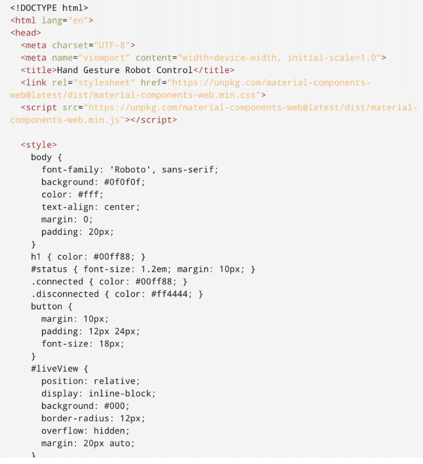
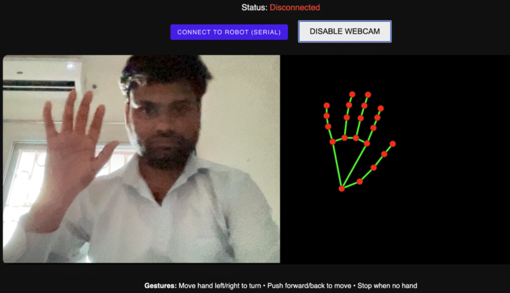
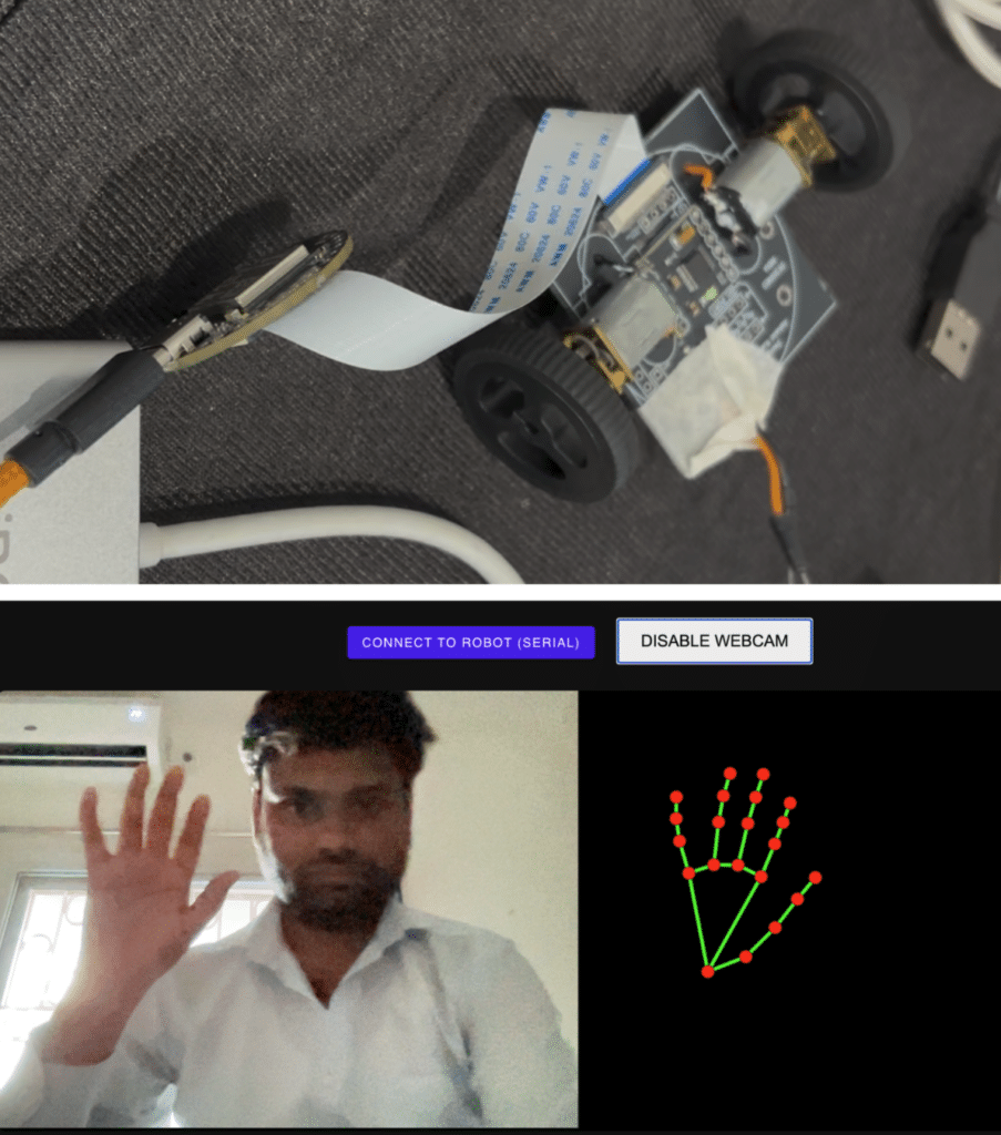
Next, the AI-based web application is developed using MediaPipe and JavaScript. The web app uses the laptop camera to capture real-time video and continuously detect hand movements. The MediaPipe AI model processes the hand landmarks and recognizes gestures based on movement and hand position. Once a gesture is detected, the corresponding command is sent to the robot through the serial port, enabling smooth real-time gesture control through a simple USB connection.
Testing Hand Gesture Controlled Mini Robot
For testing, connect the robot to the laptop using a USB cable and open the web application. Make sure to use Google Chrome or Microsoft Edge because browsers like Safari and some other browsers do not fully support camera access and WebSerial functionality.
After opening the web app, click the “Connect to Robot” button and select the correct serial port. Then click “Enable Webcam” to start the real-time camera feed. Once the webcam starts, the AI model begins detecting hand gestures, and moving your hand controls the robot in real time.
Advantages
- Extremely compact 4cm design
- Minimal wiring using FPC
- AI-based gesture control
- Expandable using I2C sensors
- Easy integration with MCU boards
- Low-cost robot development
Frequently Asked Questions
How does the robot use hand gestures for control?
The robot uses MediaPipe AI hand tracking with JavaScript and WebSerial communication.
Which motor driver is used in the robot?
The design uses the DRV8833 dual motor driver.
Can the robot work with other MCU boards?
Yes, any MCU can be connected using four signal wires or an FPC adapter.
Which browser supports the robot web application?
Google Chrome and Microsoft Edge support WebSerial and webcam access.