


In this project, you will learn how to build a 4x4x4 RGB LED CUBE that is controlled by Arduino.
RGB LED Cube Construction
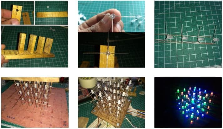
We need 64 common cathode RGB LEDs for our cube. Test all LEDs before soldering. Bend all the leads out 90 degrees apart as shown in Fig. 2.
Now construct a jig as shown in Fig. 1. Insert LEDs into the jig, then solder all 4 red led anode leads then green, and then blue. Slowly remove this pile from the jig.

We need 16 piles like this (Fig. 3). After that, take four piles from this. Connect cathodes of the first row then the second and so on. Create 4 planes like this.
Next short first cathode rows of each plane then the second and so on. As shown in Fig. 4. Insert a cube in a wooden piece or cardboard box. Solder wires on each anode’s legs: fig. 5.

RGB LED Cube Circuit Diagram
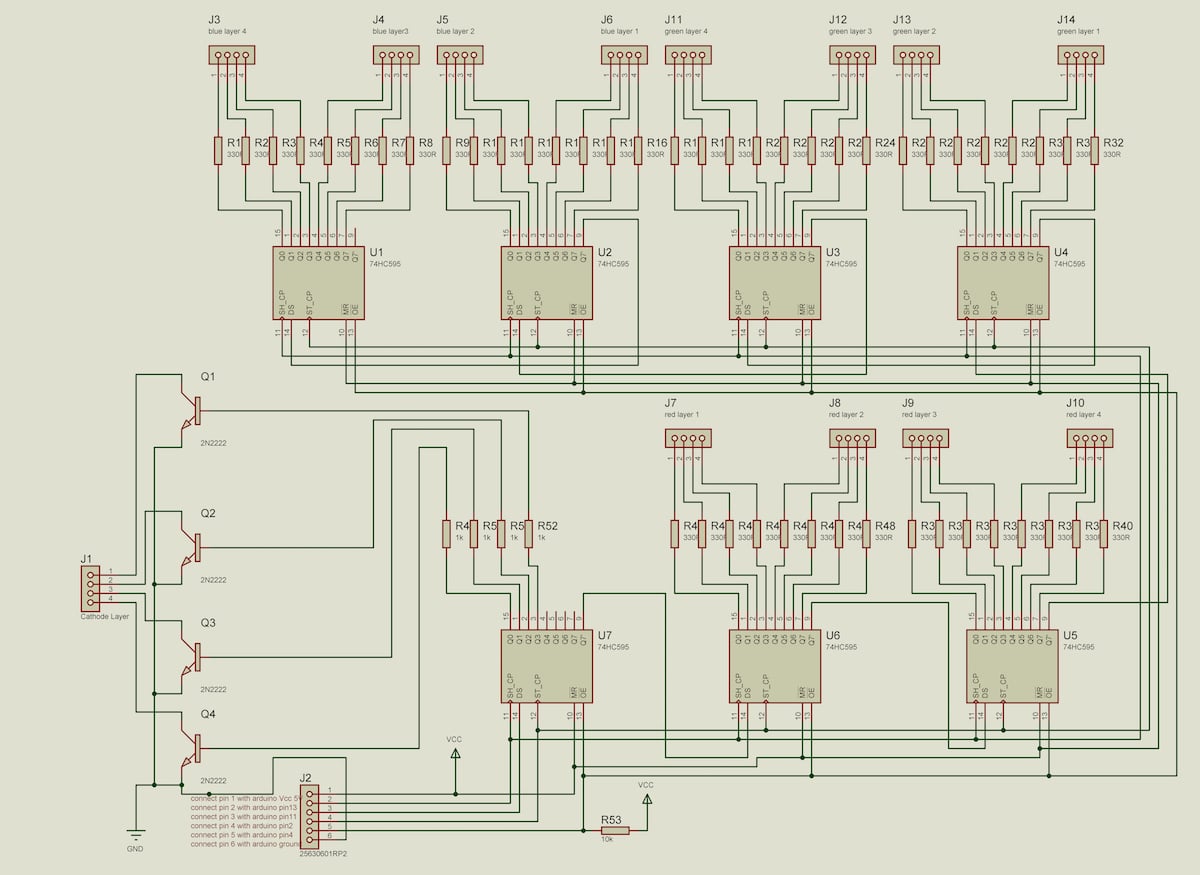
The circuit diagram of RGB LED CUBE is shown in fig:7. We have 64 LEDs in this cube and need to control each color and each led individually. So for that, we need 64*3 pins, an Arduino board can’t do that alone. But this cube construction method will help us to control each led with shift registers.
Now we need only 48+4=52 pins for controlling 64*3 LEDs, for that, we can use 7 shift registers each connected in series with Arduino. To Control each 48 LED column we can use 6nos of 74595 shift register ICs.IC 74595 is an 8-bit shift register.
ICU7 is used for multiplexing 4 cathode layers with high-current handling transistors (2n2222). 22ohm resistor is used for current limiting. Now let’s look at how the led cube connects with our control board circuit. We have 4 vertical layers of red, green, and blue LEDs.
Connect the first 4 bits of U6 with red layer 1 and the second 4 bits with red layer 2. Connect the first 4 bits of U5 with red layer 3 and the second 4 bits with red layer 4. Connect green and blue also as in the circuit diagram.
Also Check: More such interesting Mini Projects
Program
First, we need to include the SPI library that’s what’s used to shift out data to shift registers. And then we define the latch pin and the blank pin which can be any digital pins you want those go out to the shift registers.
The data and clock pins pin 11 and 13 are used by the SPI library and those are Hardware specific pins. We want to run the clock as fast as possible for the SPI so the fastest it can be is to divide the system clock by 2, so 16 Meg divided by 2 now everything’s running at eight megahertz.
We want to shift out 48+8-bit data at a time. I created a timer for multiplexing data. This timer interrupt will yank us out of the code every 124 microseconds. And this is our multiplexing frequency. It will update each cathode row data every 124 microseconds. Here BAM technique is used for controlling brightness.
The brightness of the red green and blue components of that LED on a resolution base from 0 to 15 so it’s a 4-bit resolution. With all of this data, I wrote a function to control all individual LEDs.With this function, you can write animations on your logic.
Download source code & schematics
Video Tutorial
This article was first published on 26 July 2018 and was updated on 31 August 2020.


Good work !!!
Thank you for your comment.
its really awesome.commendable
Thank you for your feedback.
how and where do i get the SPI library, you did a great job thank you