


This project is based on the AEIOU heuristic framework of Design Engineering Approach.
Design for Performance, Safety and Reliability is ensured in terms of switching module.
Design for Ergonomics and Aesthetics is ensured in terms of Priority set by the user regarding availability of Power Source.
Design for Manufacturability and Assembly is ensured in terms of Generator, Inverter and Solar Plates. Also, based upon choice and availability, different circuits using Eagle can be worked upon.
Design for Cost and Environment is addressed when costing incurred for Power Generation using Non-reneweable source can be restricted and option for clean environment is assured by Solar Source, which is a renewable source of energy
This system can be further interfaced with presently existing Mains Supply.
Cost of the Project: ₹ 1493/-
| Component Name | Component Value | Quantity |
| Resistors | ||
| R5 | 330E | 1 |
| R1,R2,R3,R4,R10 | 10K | 5 |
| JP1 | 10K SIP | 1 |
| R6,R7,R8,R9 | 1K | 4 |
| R11 | 10K PRESET | 1 |
| Capacitors | ||
| C4 | 470uF/16V | 1 |
| C3,C5 | 10uF/16V | 2 |
| C1,C2 | 33pF Ceramic | 2 |
| Integrated Circuits | ||
| IC3 | 7805 | 1 |
| IC1 | AT89S52 | 1 |
| IC2 | ULN2003 | 1 |
| Miscellaneous | ||
| Q1 | CRYSTAL 11.0592MHz | 1 |
| DIS1 | 16X2 LCD | 1 |
| LED1-LED5 | LED-RED | 5 |
| k1-k4 | 12V RELAY | 4 |
| SW1 | 2-PIN PUSH BUTTON | 1 |
| S1,S2,S3,S4 | TOGGLE SWITCH | 4 |
| JP3-JP7 | TWO-PIN PCB TIRMINAL BLOCK | 5 |
| J1 | DC POWER JACK | 1 |
| BAT1-BAT4 | 9V BATTERY | 4 |
| ADP1 | 12V ADAPTER | 1 |
Step-down transformer/12 Volt Adapter
We used an Adapter that is a step down transformer coupled with a rectifier circuit. It provides 12 V DC at the other end.
LCD (Liquid Crystal Display)
Here we used 16×2 Character LCD Displays
Size: 84mm x 44mm x 12.1mm
Character Count by Lines: 16×2
Color: Dark on Yellow-Green
Type: Character LCD
ULN2003 Relay Driver
The ULN2003 is a monolithic high voltage and high current Darlington transistor arrays. It consists of seven NPN Darlington pairs that feature high-voltage outputs with common-cathode Clamp diode for switching inductive loads. The collector-current rating of a single Darlington pair is 500mA. The Darlington pairs may be paralleled for higher current capability. Applications include relay drivers, hammer drivers, lamp drivers, display drivers (LED gas discharge), line drivers, and logic buffers.
The ULN2003 has a 2.7kW series base resistor for each Darlington pair for operation directly with TTL or 5V CMOS devices.
Features of the Driver
1) Seven Darlington per package
2) Output currents500mA per driver(600mA peak)
3) Integrated suppression diodes for inductive loads
4) Outputs can be usedin parallel for high currents.
5) TTL/CMOS/PMOS/DTL compatible inputs.
6) Inputs pinned opposite to outputs
7) Simplified layout
Relays
Relays are electromechanical devices or solid-state devices, which operate in response to a signal, which may be voltage, current, temperature etc. Electromagnetic relays operate due to magnetic fields. They are composed of two parts: (1) The operating coil and (2) The magnetic switch. When an input pulse is introduced into the coil, a magnetic field is produced in the core of the electromagnet. This action causes the switch to slide. Relays are either normally open or normally close. Relays are available for DC or AC excitation and coil voltages range from 5V to 230V.
Voltage Regulator 7805
Output Current up to 1A.
Output Voltages of 5V.
Thermal Overload Protection.
Short Circuit Protection.
Output Transistor Safe Operating Area Protection
Microcontroller AT89S52
The AT89S52 is a low power, high-performance CMOS 8-bit microcontroller with 8K bytes of in-system programmable Flash memory. The device is manufactured using ATMEL’s high-density non-volatile memory technology and is compatible with the industry standard 80C51 instruction set and pin out.
The on-chip Flash allows the program memory to be reprogrammed in-system or by a conventional non-volatile memory programmer. By combining a versatile 8-bit CPU with in-system programmable Flash on a monolithic chip, the ATMEL AT89S52 is a powerful microcontroller, which provides a highly-flexible and cost-effective solution to many embedded control applications.
The AT89S52 provides the following standard features: 8K bytes of Flash, 256 bytes of RAM, 32 I/O lines, Watchdog timer, two data pointers, three 16-bit timer/counters, a six-vector two-level interrupt architecture, a full duplex serial port, on-chip oscillator, and clock circuitry.
In addition, the AT89S52 is designed with static logic for operation down to zero frequency and supports two software selectable power saving modes. The Idle Mode stops the CPU while allowing the RAM, timer/counters, serial port, and interrupt system to continue functioning.
The Power-down mode saves the RAM contents but freezes the oscillator, disabling all other chip functions until the next interrupt or hardware reset.
Features
1) Compatible with MCS-51 Products
2) 8K Bytes of In-System Programmable (ISP) Flash Memory
3) Endurance: 10,000 Write/Erase Cycles
4) 4.0V to 5.5V Operating Range
5) Fully Static Operation: 0 Hz to 33 MHz
6) Three-level Program Memory Lock
7) 256 x 8-bit Internal RAM
8) 32 Programmable I/O Lines
9) Three 16-bit Timer/Counters
10) Eight Interrupt Sources
11) Full Duplex UART Serial Channel
12) Low-power Idle and Power-down Modes
13) Interrupt Recovery from Power-down Mode
14) Watchdog Timer
15) Dual Data Pointer
16) Power-off Flag
17) Fast Programming Time
18) Flexible ISP Programming (Byte and Page Mode)
19) Green (Pb/Halide-free) Packaging Option
Block Diagram
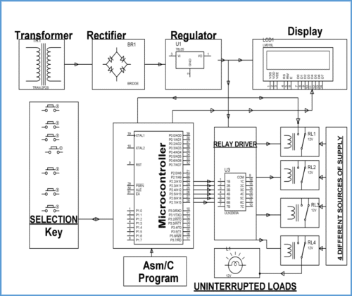
Working of the Model:
The Model works as follows:
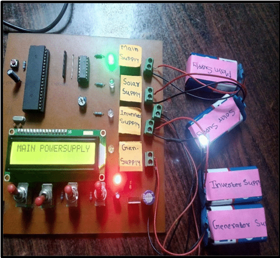
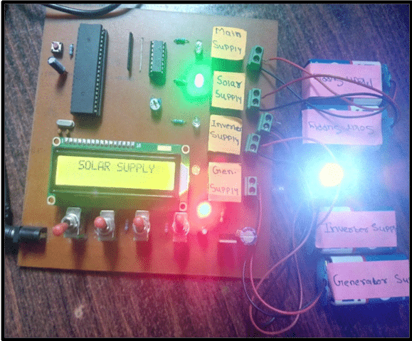
This project uses an arrangement of four different sources of supply, which are channelizedto a load to have an uninterrupted operation of the load. As System starts, it shows the Present available Supply on the LCD Screen. Then according to the Priority Predefined in the Program,switching of the Sources takes place. This system works on the pre-arranged priorities as Main Supply, Solar Supply, Inverter Supply, and Generator Supply.Four toggle switches represent four different sources respectively and are interfaced to the controller. The system decision takes place by the commands given to the relay driver i.e. ULN2003 by the programmed Microcontroller AT89S52. Accordingly, the relay driver selects which relay isto be energized.
Initially we have given high input signal to the microcontroller, so as a result the controller generates a low output to activate the first relay driver, which will result in the relay being energized and the LED glows.
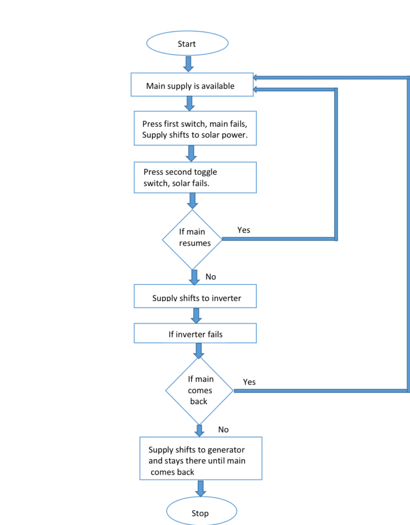
Switching takes place as follows:
1) Initially Main Supply is on so all other power sources will be off as Main supply is given the highest priority.
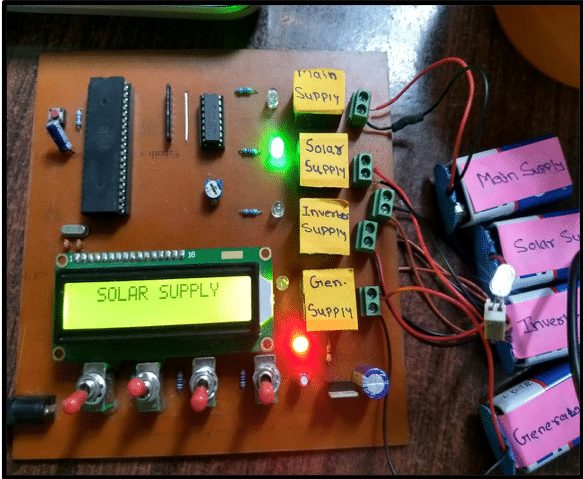
2) As soon as main turns off or power cuts off, Solar Supply will automatically be selected and the system will run on Solar Supply.
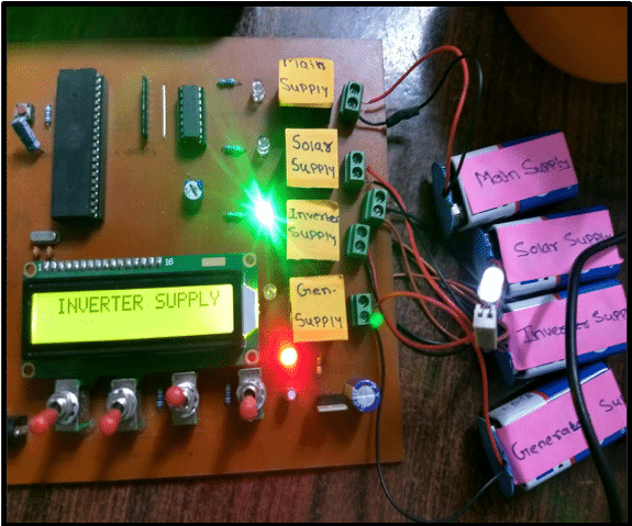
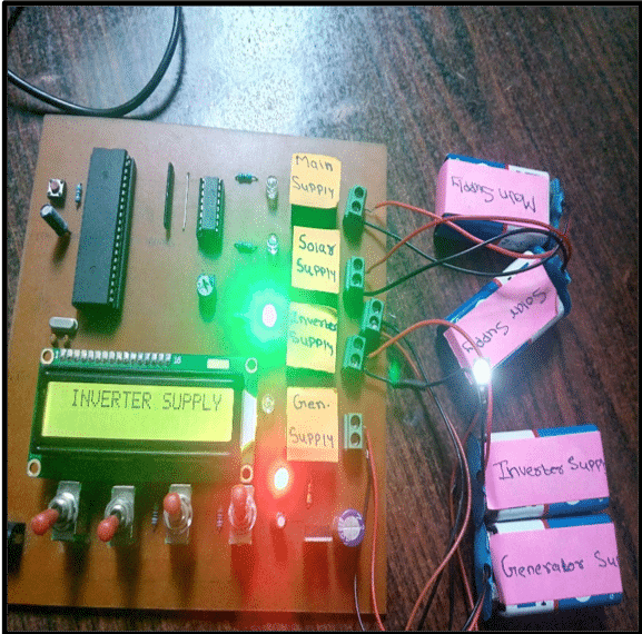
3) Now if Main as well as Solar Supply are not available, then inverter is automatically selected and the system runs on Inverter Supply.
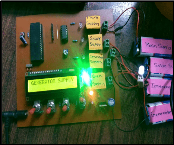
4) Finally, if Main Supply, Solar Supply, and Inverter Supply are not available, then the system will automatically switch to Generator and will run on the same.
5) Now amongst all these above-mentioned sources, if any of the source of higher priority comes back, then the system will automatically switch to that particular higher priority source.
LCD interfaced with the module displays the present Source of Energy.
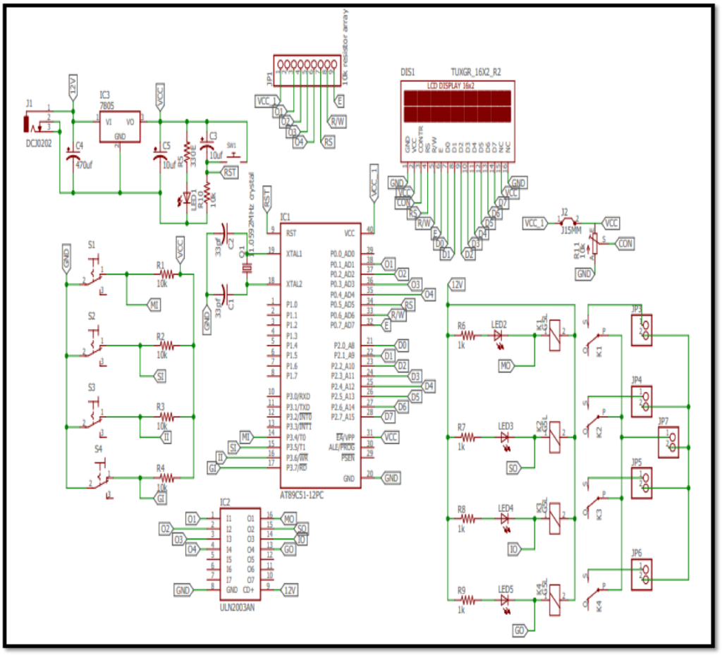
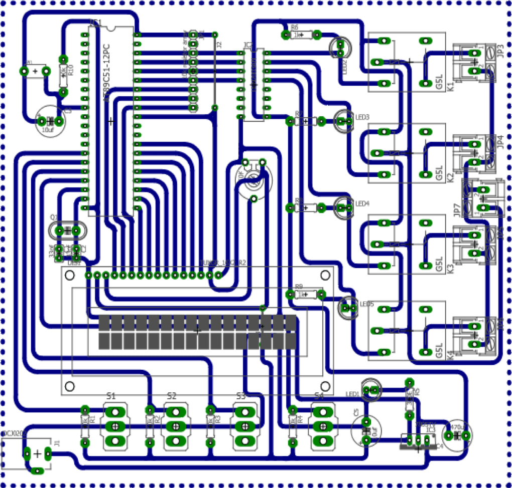
Schematic Diagram
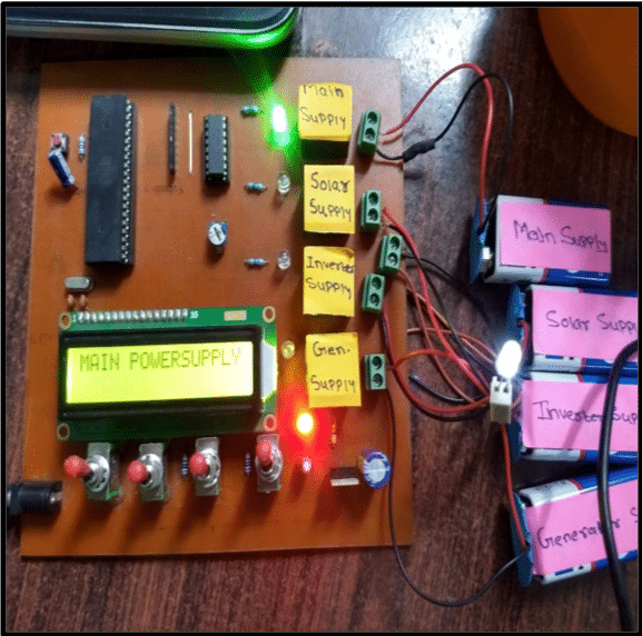
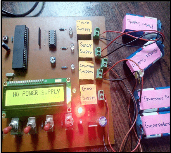
Construction & Testing
Flowchart
Software Used
1) Autodesk Eagle
– PCB Designing
2) Keil µvision
-To Program AT89S52
Code Skeleton
#include
#define lcd P2
sbit m=P3^4;
sbit s=P3^5;
sbit in=P3^6;
sbit g=P3^7;
sbit O1=P0^1;
sbit O2=P0^2;
sbit O3=P0^3;
sbit O4=P0^4;
sbit RS=P0^5;
sbit RW=P0^6;
sbit EN=P0^7;
void delay (unsigned intms) // Delay function
{
unsignedinti, j;
for (i=0; i<=ms; i++)
for (j=0; j<500; j++);
}
voidlcd_cmd(unsigned char x) //Lcd command function
{
lcd = x;
RS = 0;
RW = 0;
EN = 1;
delay(10);
EN = 0;
}
voidlcd_data(unsigned char t) // Lcd Data function
{
lcd = t;
RS = 1;
RW = 0;
EN = 1;
delay(10);
EN = 0;
}
voidlcd_initial() //Lcd initialization function
{
lcd_cmd(0x80);
lcd_cmd(0x38); //Function set: 8-bit, 2-line 5×7 dots
lcd_cmd(0x0c); //Display ON, cursor OFF
// lcd_cmd(0x0E); //Display ON, cursor ON
}
voiddisp_str(unsigned char *p) // Display String function
//*p is pointer variable
{
for(*p=0;*p!=’\0′;*p++)
{
lcd_data(*p);
}
}
void main()
{
unsigned char z;
// This initialization is to add different conditions according to your priority//
while(1)
{
if(m==1)
{
O1=1;
O2=0;
O3=0;
O4=0;
z=1;
}
if(m==…..)
{
//Add different condition here
}
// So according to the condition below mentioned task is going to be excuted
if(z==1)
{
lcd_initial();
//lcd_cmd(0x01); //Clear Display
disp_str(“MAIN POWERSUPPLY”);
lcd_initial();
}
if(z==…..)
{
//Add your lcd display task here according to the above mentioned format}
Thanks it really helped!
Can u pls share the schematics file?
Hello
Hello Smitha!!
I am really happy to help you but it would be better if your design is in your own way.
We already have provided a Schematic file for your reference. Use eagle or whatever software you feel works well for you.
Can you please send me the full coding and the schematics?
Hi Atul, all the information is present within the article itself
Hey Smitha,
we do not have the schematic file’s soft copy right now. You can you Eagle or any other PCB designing Software to make a schematic diagram
if we apply mains with 230 volts does it work
Send me the full CODING of this program .
We are using a 12v Adapter here and concert it to 4 -5v as per the needs for this circuit to work
Thanks for this wonderful project,
Can u please share the schematics drawing me [email protected] ?
I want to purchase it.. Can you give me ypur contact no. Or call me on my no. 9638328983
What is the Price for this project?
I want to buy this project
Please contact on [email protected] for components and project kits
where can i get circuit diagram for this?
I want to buy your project..
Please call me on
9369252623
Wonderful!!!
Can you please share the complete coding and the schematics drawing to [email protected]
Can you please share the complete coding and the schematics drawing to
([email protected])
Sir,
Thank you for the useful project.
“The ULN2003 has a 2.7kW series base resistor for each Darlington pair for operation directly with TTL or 5V CMOS devices.”
It should be 2.7kΩ
Cost of the Project: ₹ 1493/-
Is the cost includes GST?
Thanks for detecting this error and sharing with us.