


Most electronics enthusiasts require DC power supplies to operate various devices and accessories. The most popular and common supply is a 12V DC supply that can be easily derived from the household AC supply with transformation, rectification, filtering and stabilisation. These power supplies have a bulky steel- or iron-laminated transformer that provides a safety barrier for the low-voltage output from the AC input, and reduces the input from typically 230V AC to a much lower voltage. The low-voltage AC output from the transformer is then rectified by two or four diodes and smoothed into low-voltage DC by large electrolytic capacitors. Presented here is a 1A, 12V SMPS that can help.
A switched mode power supply (SMPS) offers the same end results at a lower cost and higher efficiency. For a given output power, an SMPS is lighter and smaller. This is because, if the frequency of operation is increased, one can get away with using a smaller core cross-sectional area. Besides, an iron-core transformer works only up to about 10 kHz, and if we need something in 50-100kHz range, we need a ferrite core.

Circuit and working
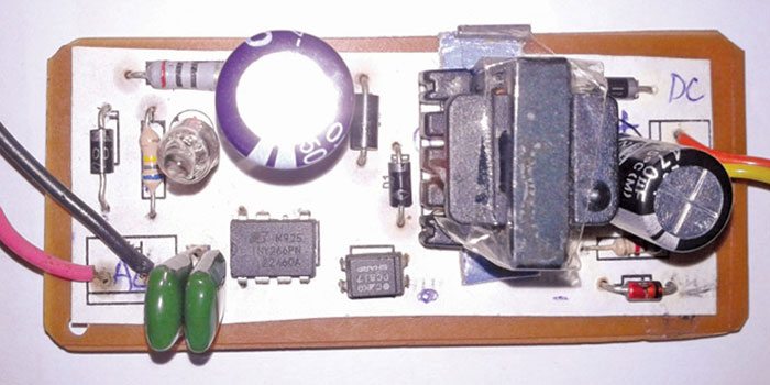
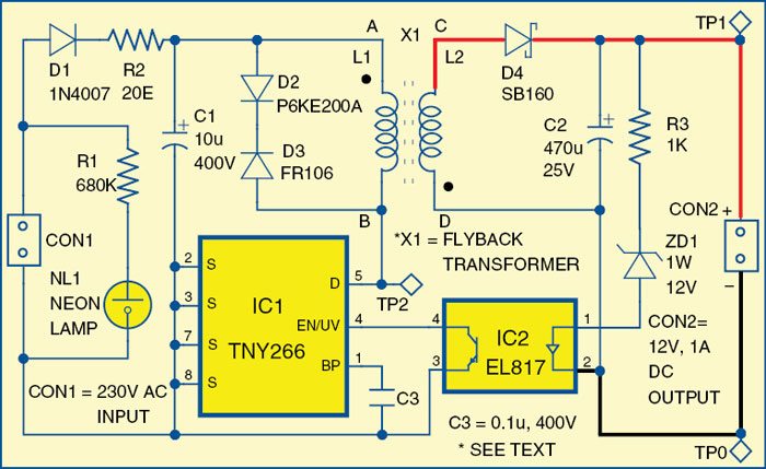
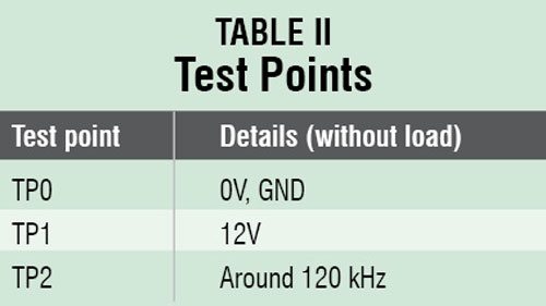 Fig. 2 shows the circuit of a simple 1A, 12V SMPS. The circuit is built around a low-power offline switcher TNY266 (IC1), photo-transistor photo-coupler EL817 (IC2), a flyback transformer (X1) and some other easily-available components.
Low-power offline switcher (TNY266). The SMPS here has been designed using a TNY266 chip, which is affectionately called the ‘555’ of SMPS. This device has a 700V power MOSFET, an oscillator, a high-voltage switched current source, a current limiting and thermal shutdown circuitry integrated onto a monolithic device. The start-up and operating power is derived directly from the voltage on the drain (pin 5), eliminating the need for a bias winding and associated circuitry. In addition, the device incorporates auto-restart, line under-voltage sense, and frequency jittering.
The drain-source breakdown voltage of the MOSFET in TNY266 is important. During the ‘off’ period, the MOSFET sees rectified 317V DC approximately. Additionally, it sees the reflected voltage of the secondary, which is about 130V AC. It also encounters the ringing voltage from the leakage inductance, and the drain-source capacitance of the MOSFET. Therefore a MOSFET with a Vdss of 650V DC is expected to keep the necessary safe operating margin. Fortunately, a MOSFET with these properties is included in TNY266.
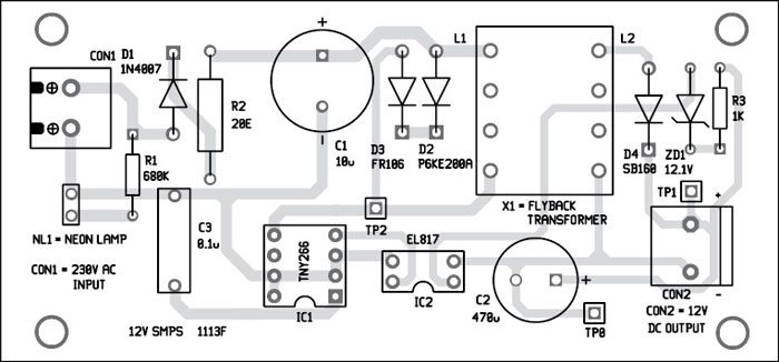
The 230V AC input is connected at CON1, which is rectified by diode D1. The neon lamp (NL1) glows when the input supply is present. Resistor R1 limits the current through the lamp. The rectified output goes to the first terminal (A) of coil L1 and the second terminal (B) is connected to the drain of the inbuilt MOSFET in IC1. Diodes D2 and D3 are essentially the snubbers, and are used to protect the MOSFET from going above 600V.
Flyback transformer
A flyback circuit is simply a pair of coupled inductors. If a current is passed through one inductor, it will store energy E = ½ (L.I2), where ‘L’ stands for inductance in henry, and ‘I’ for current in amperes. This energy can later be taken out of the second inductor, which is coupled to the former at a different volt-current ratio. The flyback’s energy storage and extraction mechanism is interesting. The key point is the polarity of the winding; the secondary is out of phase with the primary, as is evident in Fig. 2 (the dots indicate polarity).
Download PCB and Component Layout PDFs: Click here
 When the MOSFET of IC1 is ‘closed,’ the current flows through L1. Point A on L1 goes positive and by transformer action, and considering the polarity of dots, point C on L2 goes negative. This reverse biases diode D4, and no current flows in the secondary winding. Similarly, when the MOSFET is ‘open,’ the current flow through L1 is interrupted and, by Lenz’s Law, a voltage of polarity opposite to the applied voltage appears on L1 and L2. Thus, point A on L1 goes negative and point C on L2 goes positive. This situation forward biases diode D4. The energy stored in the core causes the current to flow through winding L2. This charges capacitor C2 and also powers the load. The charge on C2 is used in the next half of the cycle to keep the current through the load somewhat constant. The cycle repeats endlessly. The MOSFET is switched on/off continuously at a frequency of around 120 kHz to
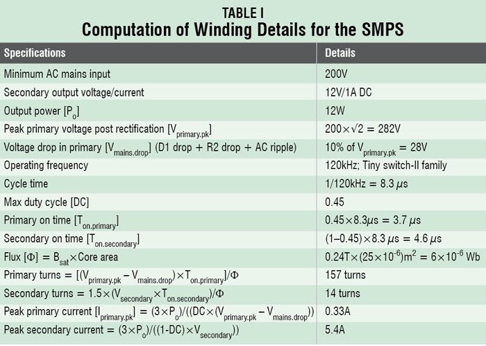
The design data for the transformer is as follows:
1. Duty cycle = 0.45 (max. duty cycle for DCM flyback = 0.5; less 10% safety margin)
2. Core saturation magnetisation Bsat = 0.24T
3. Core area of EE20 = 25mm2
Winding details computed for the SMPS are shown in Table I.
The feedback circuit
Regulated output needs feedback to control the pulse width modulation (PWM) of the MOSFET. TNY266 has a fabulous control feature; it stops the switching cycle as soon as any current is taken out of pin 4 of the device. If SMPS output exceeds the zener break-down voltage then ZD1 conducts. This lights the opto-LED and the opto-transistor grounds pin 4 of IC1, resulting in immediate stoppage of the switching cycle. Also, when the primary is conducting, diode D4 on the secondary side is reverse biased. At this time, if the voltage across D4 exceeds its reverse breakdown voltage, the SMPS will fail. Here we have used an SB160 Schottky diode with breakdown voltage= 60V.
Connector CON2 provides 12V regulated DC supply.
Construction and testing
A general core-selection ‘rule of thumb’ for SMPS below 50 watts is 2-3 mm2 core area per watt. For a primary input power of 16W, a core with a core area of 32-48 mm2 is needed. EE20 core will work well for this design.
Transformer wire
Any wire that can carry the required current can be used. To know how much current a given wire can carry, SMPS designers use a number called current density [J] for this calculation. Empirically, a good starting point is J = 5 amps/mm2. The primary carries 0.3 amps, so it can be wound using SWG 38. The secondary carries 5 amps, so it can be wound with SWG 26. A good practice would be to wind the secondary using two parallel strands of SWG 28. This reduces the skin effect. The key problem in flyback transformers is leakage inductance, which is caused by poor coupling between the primary and secondary windings. So wind them tight, with full overlap.
The air gap
Flybacks made from power ferrites must have an air gap. The energy stored in a flyback primary is E = ½ L.I2. Peak primary current depends inversely on primary inductance. An air gap increases the energy storage capacity of a flyback transformer. It is calculated as follows:
Air gap = (µ0 x N2 x Ac)/Lprimary
where:
µ0 = permeability of free space, 4π x 10-7
Ac = Core area (m2)
N = Primary turns
Lprimary = (Vprimary.pk × Ton.primary)/ Iprimary.pk
The primary inductance computes to ~3mH, so the air gap is approximately 0.2mm. However, this value is not critical, as was experienced by the authors during their experiments. Any air gap in the neighbourhood of the calculated value works well. A thin sheet of plastic or paper works fine.
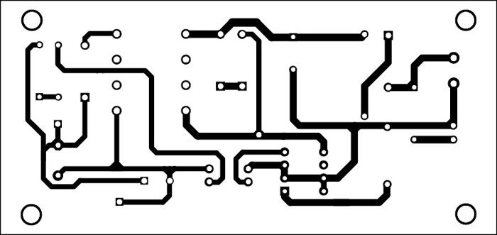
A single-side PCB for the simple 1A, 12V SMPS is shown in Fig. 3 and its component layout is shown in Fig. 4. Assemble the circuit on the recommended PCB to minimize assembly errors. Use IC base for IC1.
To test if the circuit is functioning properly, first check the regulated output at TP1 with respect to TP0. The voltage should be stable with or without a load.
Ashivini Vishvakarma is associated with IBM as a telecom systems architect and a radio amateur. Atanu Dasgupta was a powergrid executive in telecom division and is also a radio amateur.

Where can I get the transformer in market. Is there something specific I need to ask.
Dear Sir,
i have try this circuit at home but i didn’t get its out put. i check its AC &DC voltage across snubber circuit (Diode across primary side of transformer)& capacitor , it shown 696 V & 295V respectively.
i have design its ferrite core E20 transformer my self using you tube videos , but i didnt get its secondary side voltage . here i am using schottky diode SB560 insist of SB 160.
Kindly guide what is a fault in the circuit.
regards,
vipin pandey
7208446650
[email protected]
Dear Vipin.
check the secondary winding polarity
I have tried this circuit. But facing one problem. Output current is getting only less than 300mA.
Getting only less than 30KHz at TP2. Kindly help.
Sir i need this power supply..how can i get?
How come, they have not given any specific number of turns? I am novice in Inductors. Can you guys please help?
Sir what can I use exchange of ee20 core flyback transformer please reply.It will be helpful for me
Reply from author Ashvini Vishvakarma: EE20 has no replacements. It is widely available, and very cheap.
You can find it it in SMPS of every DTH set top box.
sir, give me a link of smps transformer i will buy it please …it more help
sir i need ckt diagram for this ckt
my mail id [email protected]
Hello,
If I want to operate this circuit for 200Vac to 440Vac input, then what changes should be done
Good day Sir,
Please, I need your help. I have tried building the circuit using your schematic diagram and it work, but the output I’m getting is 3V at the secondary side and it’s the highest I could get even when I increase the number of turns.
please I need 12V output, what must I do to be able to get this?
Thank you.
on which software the simulation has been performed. I already checked it on multisim and proteus but ic is not available
HOW CAN I GET 12V 3A FROM IT. WHAT SHOULD I NEED TO CHANGE AT WHAT VALUE?/
TNX
U can connect Power transistor on tny267. To handle more current
for TNY268 the max power output is about 16W at 230V input
so you need another ic for more current