


 While driving on highways, motorists should not exceed the maximum speed limit permitted for their vehicle. However, accidents keep occurring due to speed violations since the drivers tend to ignore their speedometers. This speed checker will come handy for the highway traffic police as it will not only provide a digital display in accordance with a vehicle’s speed but also sound an alarm if the vehicle exceeds the permissible speed for the highway.
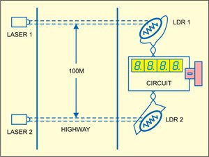
The system basically comprises two laser transmitter-LDR sensor pairs, which are installed on the highway 100 metres apart, with the transmitter and the LDR sensor of each pair on the opposite sides of the road. The installation of lasers and LDRs is shown in Fig. 1. The system displays the time taken by the vehicle in crossing this 100m distance from one pair to the other with a resolution of 0.01 second, from which the speed of the vehicle can be calculated as follows:
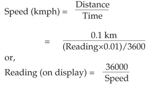

As per the above equation, for a speed of 40 kmph the display will read 900 (or 9 seconds), and for a speed of 60 kmph the display will read 600 (or 6 seconds). Note that the LSB of the display equals 0.01 second and each succeeding digit is ten times the preceding digit. You can similarly calculate the other readings (or time).
Speed checker circuit diagram
Figure below shows the circuit of the speed checker. It has been designed assuming that the maximum permissible speed for highways is either 40 kmph or 60 kmph as per the traffic rule.

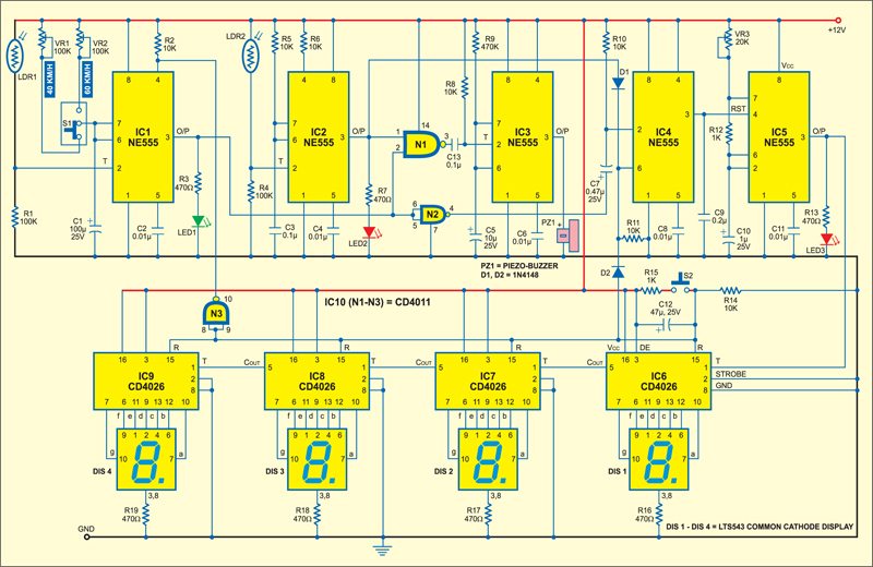
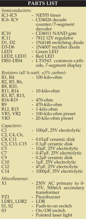
The circuit is built around five NE555 timer ICs (IC1 through IC5), four CD4026 counter ICs (IC6 through IC9) and four 7-segment displays (DIS1 through DIS4). IC1 through IC3 function as monostables, with IC1 serving as count-start mono, IC2 as count-stop mono and IC3 as speed-limit detector mono, controlled by IC1 and IC2 outputs. Bistable set-reset IC4 is also controlled by the outputs of IC1 and IC2 and it (IC4), in turn, controls switching on/off of the 100Hz (period = 0.01 second) astable timer IC5.
Circuit description
The time period of timer NE555 (IC1) count-start monostable multivibrator is adjusted using preset VR1 or VR2 and capacitor C1. For 40kmph limit the time period is set for 9 seconds using preset VR1, while for 60kmph limit the time period is set for 6 seconds using preset VR2. Slide switch S1 is used to select the time period as per the speed limit (40 kmph and 60 kmph, respectively). The junction of LDR1 and resistor R1 is coupled to pin 2 of IC1.
Normally, light from the laser keeps falling on the LDR sensor continuously and thus the LDR offers a low resistance and pin 2 of IC1 is high. Whenever light falling on the LDR is interrupted by any vehicle, the LDR resistance goes high and hence pin 2 of IC1 goes low to trigger the monostable. As a result, output pin 3 goes high for the preset period (9 or 6 seconds) and LED1 glows to indicate it. Reset pin 4 is controlled by the output of NAND gate N3 at power-on or whenever reset switch S2 is pushed.
For IC2, the monostable is triggered in the same way as IC1 when the vehicle intersects the laser beam incident on LDR2 to generate a small pulse for stopping the count and for use in the speed detection. LED2 glows for the duration for which pin 3 of IC2 is high.
The outputs of IC1 and IC2 are fed to input pins 2 and 1 of NAND gate N1, respectively. When the outputs of IC1 and IC2 go high simultaneously (meaning that the vehicle has crossed the preset speed limit), output pin 3 of gate N1 goes low to trigger monostable timer IC3. The output of IC3 is used for driving piezobuzzer PZ1, which alerts the operator of speed-limit violation. Resistor R9 and capacitor C5 decide the time period for which the piezobuzzer sounds.
Circuit operation
The output of IC1 triggers the bistable (IC4) through gate N2 at the leading edge of the count-start pulse. When pin 2 of IC4 goes low, the high output at its pin 3 enables astable clock generator IC5. Since the count-stop pulse output of IC2 is connected to pin 6 of IC4 via diode D1, it resets clock generator IC5. IC5 can also be reset via diode D2 at power-on as well as when reset switch S2 is pressed.
IC5 is configured as an astable multivibrator whose time period is decided by preset VR3, resistor R12 and capacitor C10. Using preset VR1, the frequency of the astable multivibrator is set as 100 Hz. The output of IC5 is fed to clock pin 1 of decade counter/7-segment decoder IC6 CD4026.
IC CD4026 is a 5-stage Johnson decade counter and an output decoder that converts the Johnson code into a 7-segment decoded output for driving DIS1 display. The counter advances by one count at the positive clock signal transition.
The carry-out (Cout) signal from CD4026 provides one clock after every ten clock inputs to clock the succeeding decade counter in a multidecade counting chain. This is achieved by connecting pin 5 of each CD4026 to pin 1 of the next CD4026.
A high reset signal clears the decade counter to its zero count. Pressing switch S2 provides a reset signal to pin 15 of all CD4026 ICs and also IC1 and IC4. Capacitor C12 and resistor R14 generate the power-on-reset signal.

The seven decoded outputs ‘a’ through ‘g’ of CD4026s illuminate the proper segment of the 7-segment displays (DIS1 through DIS4) used for representing the decimal digits ‘0’ through ‘9.’ Resistors R16 through R19 limit the current across DIS1 through DIS4, respectively.
The above circuit shows the power supply. The AC mains is stepped down by transformer X1 to deliver the secondary output of 15 volts, 500 mA. The transformer output is rectified by a bridge rectifier comprising diodes D3 through D6, filtered by capacitor C14 and regulated by IC11 to provide regulated 12V supply. Capacitor C15 bypasses any ripple in the regulated output. Switch S3 is used as the ‘on’/‘off’ switch. In mobile application of the circuit, where mains 230V AC is not available, it is advisable to use an external 12V battery. For activating the lasers used in conjunction with LDR1 and LDR2, separate batteries may be used.
Speed checker construction and working
Assemble the circuit on a PCB. An actual-size, single-side PCB layout for the speed checker and its component layout is shown below.


Download PCB and component layout PDFs: click here
Before operation, using a multimeter check whether the power supply output is correct. If yes, apply power supply to the circuit by flipping switch S3 to ‘on.’ In the circuit, use long wires for connecting the two LDRs, so that you can take them out of the PCB and install on one side of the highway, 100 metres apart. Install the two laser transmitters (such as laser torches) on the other side of the highway exactly opposite to the LDRs such that laser light falls directly on the LDRs. Reset the circuit by pressing switch S2, so the display shows ‘0000.’ Using switch S1, select the speed limit (say, 60 kmph) for the highway. When any vehicle crosses the first laser light, LDR1 will trigger IC1. The output of IC1 goes high for the time set to cross 100 metres with the selected speed (60 kmph) and LED1 glows during for period. When the vehicle crosses the second laser light, the output of IC2 goes high and LED2 glows for this period.
Piezobuzzer PZ1 sounds an alarm if the vehicle crosses the distance between the laser set-ups at more than the selected speed (lesser period than preset period). The counter starts counting when the first laser beam is intercepted and stops when the second laser beam is intercepted. The time taken by the vehicle to cross both the laser beams is displayed on the 7-segment display. For 60kmph speed setting, with timer frequency set at 100 Hz, if the display count is less than ‘600,’ it means that the vehicle has crossed the speed limit (and simultaneously the buzzer sounds). Reset the circuit for monitoring the speed of the next vehicle.
Note. This speed checker can check the speed of only one vehicle at a time.

All the time i used to switch on my speed checker circuit using Ne555, the circuit did not work…Pin 7 and Pin 8 of 555 get shorted,,, thus the circuit is not working. Could anyone please tell me what is the reason behind it? and also provide me the suggestion about what to do so that the circuit can work properly… as soon as possible..
There is no way pin 7 and 8 of NE555 should be shorted. Have you double checked the circuit as per the diagram given here? You get the complete kit of this project available at Kits ‘n’Spares. Please visit http://kitsnspares.com/user1/productdescription.asp?id=37
Can u plz send me the pic of the project after completion ……….i dint understand the connection of ldr and laser light
I have completed the project on bread board because it’s not working properly on vero board. The connection for ldr and laser is simple. You have to use ldr on the main circuit. The necessity of Laser is here to reduce the resistance of the ldr. You can use any light source, it’s not mandatory you only have to use laser. Make the circuit. For, working video you can use youtube because it would be better than Circuit Image. Good Luck.
hi…. im using this circuit as my project but the output is not showing my teacher said that i have to check part by part and each part should be a square wave but the output ive got was a sine wave … im sure that my connections r right ( im using breadboard as well) so, can u tell me please what was the output you have got for each part ??
One complete cycle
Kit is not working…….i have tried for 2 times….the pbc design is not wrong
dude we thought you tested the components before u send them from now on i am never going to recommend any one this.your kits cost only 1000 rs but you take much higher amount.very bad.u put us in a difficult situation
Hi Akhil,
Regret for inconvenience. We are checking components, but randomly. You are requested to let us know the name of componets to send replacement. Also proivde your Order ID for the same.
Hello
i wanted to know whether the switch used here is 2 pin or 3 pin. Also how do i check if my connections are right part by part because if i apply power supply at one go the whole thing could burn due to improper connections.
And is there video demonstrating the working according to the given circuit diagram?
thank you.
where is the ic11 used(l7812cv)?
IC11 is shown in power supply section on next page.
There is no clarity in the circuit diagram.
Please reload the page.
You tricked us!!
we asked for a 555 timer and nand gate based circuit but, were delivered an entirely different circuit (microcontoller based). Though, all the specification of that other circuit were mentioned but , they were incorrect too.
We request you to please rectify your blunder mistake!
Waiting in anticipation.
I have rectified the problem. Input voltage (Vdd) and ground (Gnd) for “ALL” IC 4011 should be given for the circuit to work I hope the circuit diagram is changed. Thank me later just do the connections and see your circuit work!
1 more problem I used ir transmitter led and receiver led instead of the ldr.
I’m having problem setting the resistance values for the variable resistors VR1,VR2,VR3. Please help me EFY Team!
Hii, my circuit connection are comple as per circuit diagram but only seven segment display is on.no speed measure when two lasser are intrupt.no one result.
For practical application, if we want to use the circuit on highways,will the circuit work?
I am asking because LDR will get different intensity in day and night.
Thanks!
Sir please explain each part of block diagram clearly ,timers and counters and all parts in project speed checker to detect Rash driving warning system for highways using 555 timer.
Why their is no supply for one LED?
The details on circuit and its working have been explained in text. Each LED will get supply voltage whenever the corresponding output pin 3 of 555 IC becomes high. So there is not need of separate power supply in any of the LEDs in the circuit.
hey can i know why u have used those capacitors and resistors with that particular values .I would like to know as i am doing this project now as a mini project and also i would like to know LDR receiving signal procedure ..its very important for me to do this..i would like to modify it as well ..hope u respond thank u
k
This circuit is working fine
Do you have video of your project
Sorry, as of now video tutorial is not available for this project.
We have some querry regarding this project plz give us your email id or contact number
By which software you made the circuit of project.
I want a vedio of how to made connections for this project pls anyone respond
Pls send me a vedio of how connections are made
I can pay you through PayPal I need whole information regarding this project, I have made the circuit on breadboard but circuit just switches on and segments show zeros nothing else.
Can this circuit be simulated using any simulation software like Proteus? If yes, then how?