


Most of the laboratories and educational institutions in need of accurate stopwatches for precision time measurement and this kind of devices are rare and costly. Here this simple DIY stopwatch project focuses on the construction of a stopwatch with 0.01 second accuracy. This stopwatch can be used for sports events by connecting a sensor to the CN6 and CN7 connectors.
Stopwatch Circuit Diagram and Working
The Fig.1 shows the circuit diagram of the stopwatch. The circuit is powered from 230V AC via a step-down transformer TR1. The 9 V output of TR1 rectified by Diodes D1 and D2 and smoothed by capacitor C1and C4. The rectified DC voltage regulated to 5V by the regulator IC U1 and fed to microcontroller circuit.
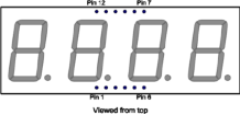
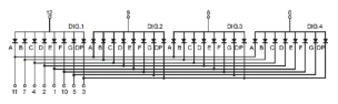
The controller IC 89c4051 running at an oscillator frequency of 12MHz by connecting a crystal CR1. Switch S1 used to ON and OFF the power to the circuit. Capacitor C2 and C3 connected for suppressing high frequency signal generated by IC1. C6 and C7 are decoupling capacitors for the crystal. C5 and R13 are power on reset circuit for the micro-controller IC. Switch S2 connected as manual reset for the controller and used to reset the counter to zero. S3 is used start and stop the stopwatch. A four-digit multiplexed seven segment display used as a display for the hardware simplicity and economical benefit.

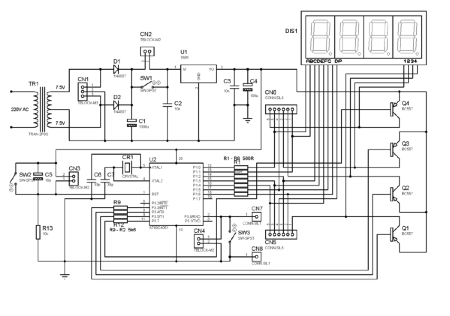
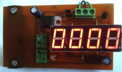
When switch S1 closed the display indicates 0000. On closing switch S3 the display starts counting up to the moment at which switch S3 opened. The display indicates the last count value till the reset button S2 depressed.
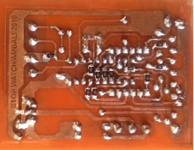
PCB Designs
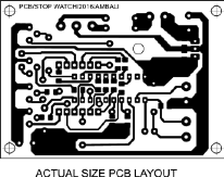
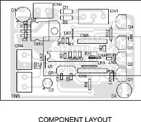
The actual size PCB layout is shown in fig.2 The PCB can be manufactured from local PCB manufacturers using the attached PCB design file in PDF format. Assemble the circuit on the PCB and check for any short circuits. Special care should be taken while soldering SMD components.

Software
The software is written in ‘C’ language and compiled using Kiel software. The delay in C language is depends on compiler sometimes a small correction may be required on delay loop for calibration purpose.
Download source code
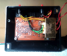
Assembling and Testing
Assemble the circuit on the PCB and cross check for any wrong connections. Burn the program (hex file) to the controller using suitable programmer. Insert the controller IC 89c4051 on the IC base. Fix PCB, switches, connectors and LED’s in a general purpose cabinet. Switch on the unit by closing switch S1.
Ensure that the seven-segment display shows study reading of ‘0000’, if not again check the circuit for any mistakes. Close switch S2 the display will start counting. Open the switch S2 the display indicates the duration of the switch S2 closed condition. If the switch S2 closed again the display start counting from the last count value. Depress S3 for reset the display.
Compare duration with a calibrated stopwatch. If the reading found out of calibration adjust the delay loop till exact timing attained. For household purposes no need of calibration but laboratory purposes it recommended to calibrate the unit. Terminal connector CN7 and CN8 are provided for replacing the switch S2 with an external switch.
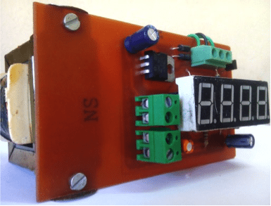
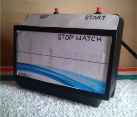
DIY Stopwatch Prototype
Check other tested diy Stopwatch projects