


 This is a simple transistor’s output characteristic curve-tracer program through PIC microcontroller & USB interface using Python programming language. Output characteristic curve of a transistor is automated using Python software and USB interface. The application software for collecting the measured value and displaying it on the monitor screen is developed using Python.
Types of USB
In recent PCs, legacy ports such as parallel port, serial port and so on have been replaced with USB. A USB’s plug-and-play feature can be used to automate laboratory instruments/data-acquisition systems. To meet the needs of various applications using USB interface, three speeds of operation have been designed in USB V2.0 specification, namely, low speed (1.5Mbps), full speed (12Mbps) and high speed (480Mbps).
Recently, USB3.0 specification has introduced super speed with 5Gbps.The physical USB connection uses four wires. Two wires are used to carry the differential signal (D+ and D-), and the other two are for power and ground. To transfer data between the host PC and the device USB V2.0 supports four types of data transfers, namely, control, bulk, interrupt and isochronous.

Control transfer is mainly used to configure a device when it is first connected to the PC. The process of configuration is known as enumeration. It is defined as the initial exchange of information by which the host learns about the device and assigns an appropriate device driver.

Bulk data transfers are used when data is generated or consumed in relatively large quantities.
Interrupt data transfers are used for timely but reliable delivery of data.
Isochronous data transfers occupy a pre-negotiated amount of USB bandwidth with pre-negotiated delivery latency (also called streaming real-time transfers).
One of the major barriers to designers of USB peripherals is developing device drivers for custom-built USB devices. This has been removed with the use of LibUSB-Win32, which is an open source driver.
Host software
USB supports master-slave configuration. Master is always the PC. Software that resides and controls the communication flow in the PC is known as host software. In this article, the host software used to communicate with the USB mass storage class/communication device class is Python.
Python is an interpreted language, which can save considerable time during program development because no compilation and linking are necessary. It is a popular programming language used for both standalone programs and scripting applications. It is free, portable, powerful and remarkably easy to use.
The interpreter can be used interactively, which makes it easy to experiment with features of the language. Programs written in Python are typically much shorter than equivalent C or C++ programs. There are two ways to use the interpreters, namely, interactive mode and script mode. In interactive mode, the interpreter prints the result as the program is typed.
The chevron, >>>, is the prompt the interpreter uses to indicate that it is ready. Alternatively, you can store the code in a file and use the interpreter to execute the contents of the file, which is called a script.
Software required
The required software include Python 2.5 (python-2.5.2) or higher IDE, Win32 Python (pywin32-210.win32-py2.5), Matplot Library (matplotlib-0.91.2.win32-Py2.5), Numeric Python (numpy-1.0.4.win32-py2.5) and PyUSB-1.0.0a2.
PyUSB-1.0.0a2 is a Python library allowing easy USB access. PyUSB-1.0.0a2 version is written in Python, which allows Python programmers with no background in C to understand how PyUSB works. PyUSB can run on any platform with Python 2.4 and later version. Communicating with a USB device has never been so easy. USB is a complex protocol, but PyUSB has all the necessary functions needed to configure a USB-supported device. PyUSB modules have two sub-modules: usb.core as the main module and usb.util containing utility functions.
PyUSB 1.0 tutorial gives the basic information about the complex USB protocol. If you want to know all information related to USB, refer the books USB Design by Example by John Hyde and USB Complete by Jan Axelson.
Functions needed for USB configuration and data acquisition are incorporated in pic18f4550.py, namely, __init__(self,val1,val2), set_portb_output(self,val), set_portd_output(self,val), read_analog_0(self), read_analog_1(self) and set_voltage12(self, val).
Details are as follows:
• __init__(self,val1,val2) takes care of USB communication.
• set_portb_output(self,val) helps set port B values from 0 to 255.
• set_portd_output(self,val) helps set port D values from 0 to 255.
• read_analog_0(self) helps read analogue values from channel 0.
• read_analog_1(self) helps read analogue values from channel 1.
• set_voltage12(self, val) helps send a 12-bit value to DAC MAX5154.
Software installation
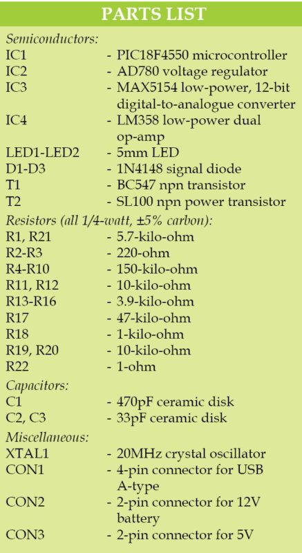
Install Python2.5.2 IDE or higher in Windows 7 operating system. Then, install the supporting tools one by one. Default folder is C folder (C:Python25). Extract PyUSB-1.0.0a2 zip file to Python25 folder. Now, using Command Prompt, go to PyUSB folder, which is inside Python25 folder, and install PyUSB using the following command (also shown in Fig. 1):
>python setup.py install
Having installed the necessary software, place pic18f4550.py and efy_trans.py files inside Python25 folder.
Circuit and working
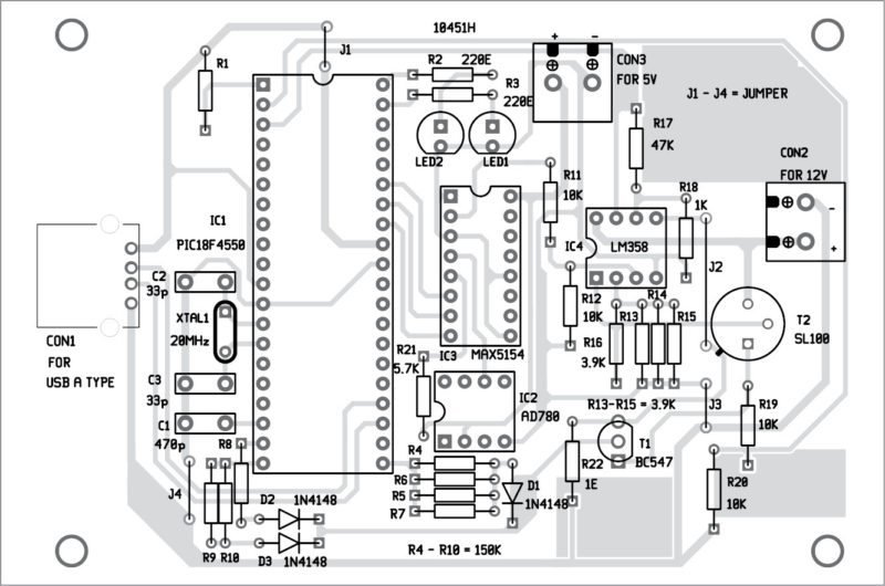
Circuit diagram of the USB interface using Python and transistor curve tracer is shown in Fig. 2. It is built around PIC18F4550 microcontroller, MAX5154 12-bit digital-to-analogue converter, voltage regulator AD780, voltage amplifier LM358, current-to-voltage converter OP741, power transistor SL100/CL100, transistor under study BC547 (T1) and other essential components needed for USB configuration.

The microcontroller has an on-chip USB transceiver, which is connected to the host PC through a USB cable. Clock frequency required for full-speed USB operation is derived from external 20MHz crystal. A pull-up resistor internal to the microcontroller configures the USB device as a full-speed device. In this design, power required for PIC18F4550 operation is drawn from the bus.
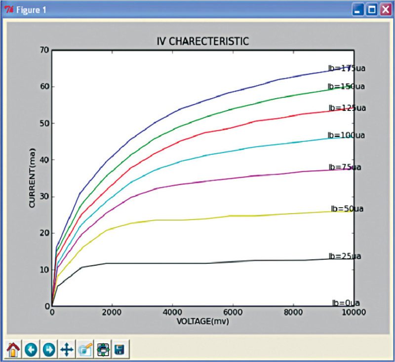
Base current of the transistor under study is varied from 0µA to175µA in eight steps using port D pins (D0, D1 and D2). Collector voltage is varied from 0V to 2.5V in eight steps to the digital-to-analogue converter from port B.
Output voltage from the digital-to-analogue converter is subsequently amplified about four times using LM358 and given to the base of the power transistor. Emitter of power transistor SL100 is connected to the collector of the transistor whose voltage is being varied.
Collector voltage is given to channel 0 of the built-in analogue-to-digital converter after dividing the voltage exactly by half using a potential divider arrangement to meet the voltage limitation of the microcontroller. Assuming that collector current is equal to emitter current, output is taken across the one-ohm resistance, and drop across one-ohm resistance is amplified about 50 times and given to channel 1 of the built-in analogue-to-digital converter.
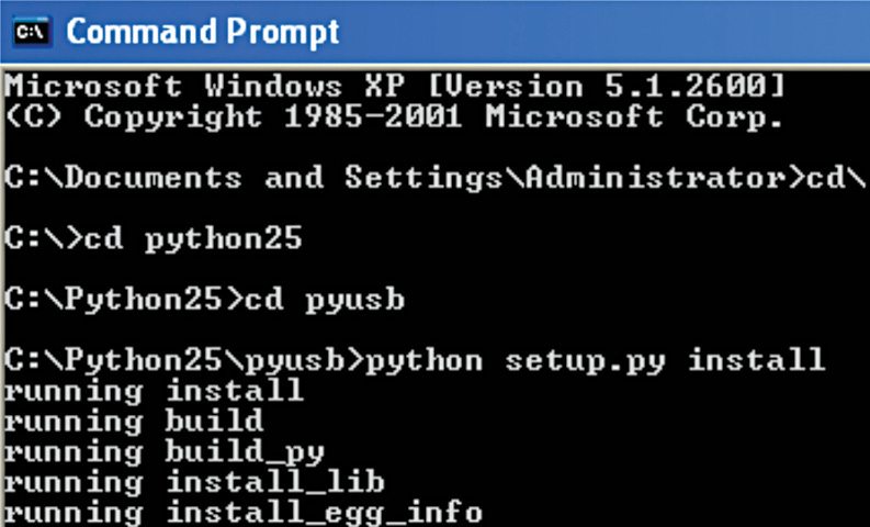
The author’s prototype is shown in Fig. 3.
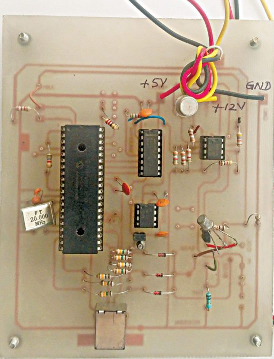
Construction
An single-side PCB layout for the USB interface is shown in Fig. 4 and its component layout in Fig. 5. After assembling the circuit on the PCB, enclose it in a suitable box.
Download PCB and Component layout PDFs: Click here
Firmware
All USB devices handle a standard set of requests, described in the USB specification. It is implemented using pic18_usb header file provided in CCS C compiler. The compiler provides the basic framework for enumeration. During enumeration, the host requests data structures called descriptors from the device. These descriptors contain information about the USB device and type of communication. If you want to design your own USB device, be aware of the endpoint details, vender IDs and product IDs. This information is necessary for device enumeration and is given in usb_desc_cdc1.h file. The firmware, in addition to USB requirement, implements the following tasks:
- Generates different base voltages
- Generates different emitter currents
- Measures collector voltages
- Sends data to PC
The USB host communicates with the USB peripheral through the device driver. The device driver is a software component that enables an application to access a hardware device. USB device drivers for Windows must conform to Win32 driver model.
Windows includes application programmer’s interface functions that enable applications to communicate with device drivers. The device driver is generated using Library USB Wizard, and the device is installed in the host computer. Libusb-win32 is a port of the USB library for Windows operating system. The library allows user space applications to access any USB device on Windows in a generic way without writing any line of kernel driver code.
Hardware installation procedure
Step 1
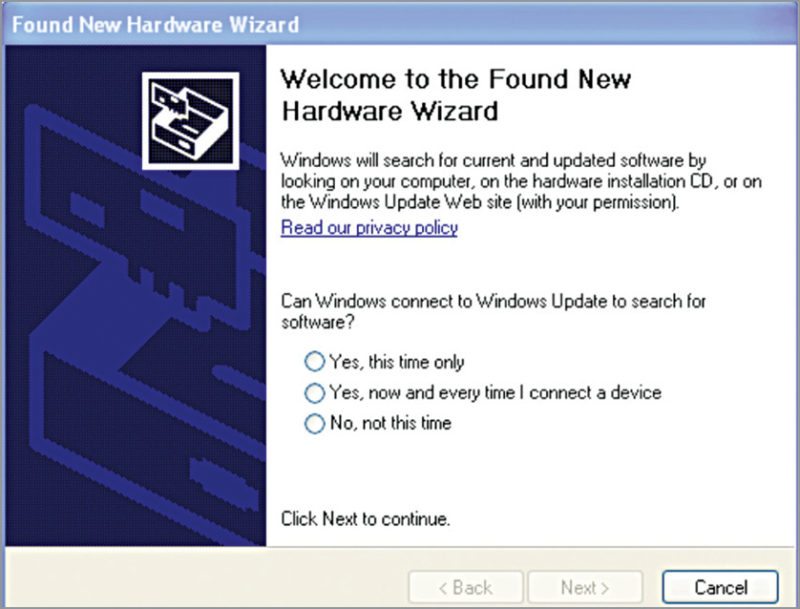
After fusing the program (hex file) into the microcontroller, connect the board to the PC. As soon as the two are connected, a pop-up screen appears, as shown in Fig. 6.
Step 2
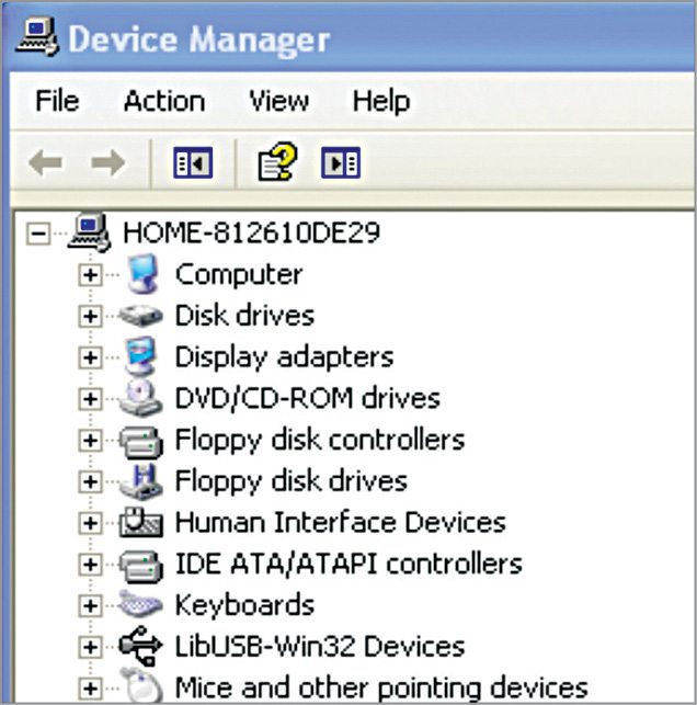
Use inf- wizard found in libusb-win32-device-bin-1.2.6.0 folder to generate the driver for the attached device. If the driver is installed properly, the attached device will appear in Device Manager, as shown in Fig. 7.
Step 3
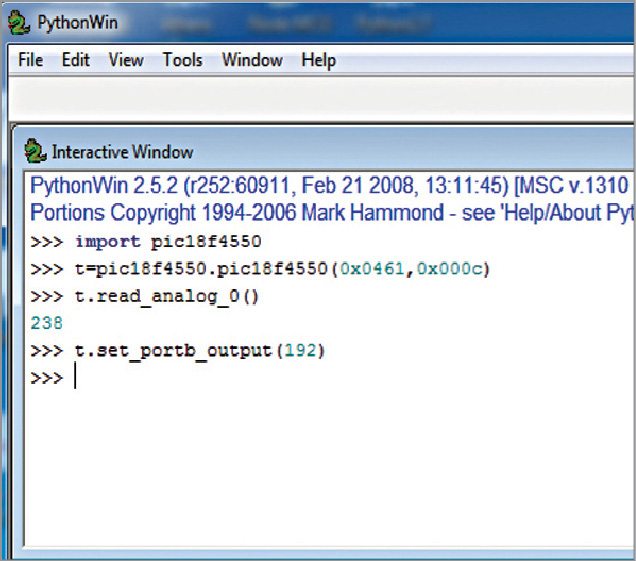
Basic functions including USB configuration, setting port B bits and reading analogue voltages can be tested using default interactive Python window. Using set_portb_output (192) command, connected LEDs (LED1 and LED2) can be lit.
Similarly, analogue voltages can be measured by connecting the terminal (AN0) to 5V. The value corresponding to 5V is 255. It is better to test the basic function using interactive Python window (Fig. 8) before testing the actual board.
Step 4
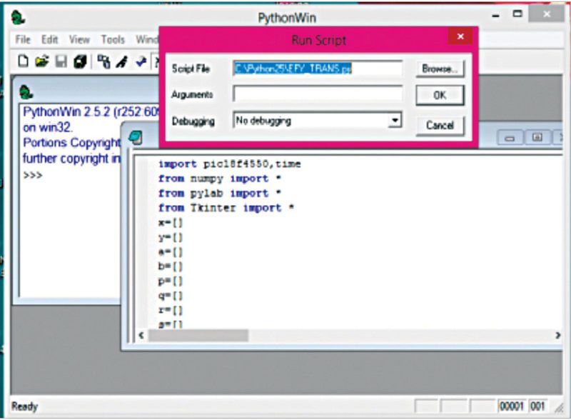
Open efy_trans.py file from PythonWin 2.5.2 Interactive Window and run the script as shown in Fig. 9. The program output pattern is displayed using Tkinter software, which is shown in Fig. 10.
The USB based data-acquisition system using Python interface and open source general purpose device driver reduces the complexity involved in USB connectivity. Interactive nature of Python software makes USB connectivity more user-friendly as compared to other visual languages.


I need PC Oscilloscope USB interfacing Hardware & Software for Project work may be qty more than 5 spices
India Make