


 Smartphones have become an integral part of our lives but when it comes to watching our favourite TV shows, we have to look for the TV and set-top box remotes. Why not build the functionality of a TV and a set-top box remote in your smartphone? This project explores the possibility.
How a remote works
The functional diagram of a remote controller is shown in Fig. 1, which has following blocks.
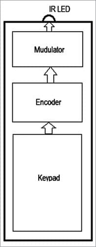
The keypad
The remote has several keys which, when pressed, instruct the TV/set-top box to perform a specified function. On pressing a key, the key-scan code for that key is passed on to an encoder.
The encoder
You would have noticed that the remote of one brand or product does not work for another brand. For example, you cannot use the remote of a Sony TV to operate an LG TV. This happens as each brand of remote assigns a unique code to its keys.
The remote controller is a serial device that transmits the code bits serially, one bit after the other. The sequence in which these bits are transmitted is also important. For example, while transmitting code 100100, the bits can either be sent out as 1-0-0-1-0-0 or in the reverse order as 0-0-1-0-0-1. This gets a bit complicated when additional bits like start bit and end bit, error correction, etc have to be added. All such rules together are called a protocol.
The encoder translates the key-scan code to the manufacturer-specified corresponding code and packages it as per the prescribed protocol.
The carrier generator and modulator
A remote controller can use radio waves, Bluetooth, Wi-Fi, or infrared (IR) waves to communicate with the TV set. Most remotes use IR waves.
Infrared is part of the electromagnetic wave spectrum and very similar to light, though with a higher wavelength. This similarity causes problems as infrared waves are present everywhere, be it sunlight or a warm body.
The solution lies in using a carrier wave to carry the message. IR remotes use a carrier wave in the 30-40MHz range, the most common being the 38MHz frequency.
The code being sent is made to piggyback on this carrier wave by way of pulse modulation. The TV receives these waves and recovers the remote code through a demodulator. The process is similar to radio signals where the audio signals piggyback on a radio frequency carrier wave and after the radio receiver tunes in on to them, demodulates it, restoring the audio signals.
The IR emitter
The IR emitter is an infrared LED that switches on and off at 38MHz in sequence with the carrier wave, thereby generating a pulsating infrared wave. This signal is received by the TV, which has an infrared receiver. The signal is demodulated by removing the 38MHz carrier and the code transmitted by the remote is recovered. Action is now taken based on the code transmitted. The IR signal transmission is shown in Fig. 2.

Project outline
In the current project, we shall be making a Wi-Fi-enabled remote controller which would replace the TV and set-top box remote and add greater functionality to it. We shall not be making any physical changes to the mobile phone or TV set. The functional diagram of our Wi-Fi remote is shown in Fig. 3.

The project involves building an Android app and decoding the TV/set-top box remote.
Android app development
The Android app is built using MIT App Inventor. Follow the steps below to download and install the app on your mobile.
- Download the file TVRemote_Ver1_4.apk from below to your mobile phone.
- Go to Security settings on your phone and enable ‘Allow installation of apk files from unknown sources.’ Since this program is built by us only, there is no risk of loading it. Click on the TVRemote_Ver1_4.apk file in your Downloads folder to begin the installation.
- Change the ‘Allow installation of apk files from unknown sources’ setting back to the original state to restore the original settings.
The app should now be ready for use. The app icon will look as shown in Fig. 4.

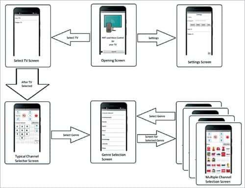
The app – first look
The app begins by displaying the Opening Screen message. You are presented with two options: Settings (by way of a sprocket icon) and the Select TV button. The app is designed to work on multiple TVs you may have at home. The IR transmitter module is separate for each TV and has its own IP address.
Press the Settings option (sprocket icon) in the app to open the Settings screen. Here you can set up the TV names and IP address of respective IR-Blasters (explained later in the article). The app supports multiple TVs/IR-Blasters you may have. The Settings screen allows you to Add, Modify, Delete, and Clear All.
You can return to the opening screen by pressing the Cancel/Back button. The list of available TVs is shown, and you can select a TV name to modify its existing TV IP address.
The option Select TV will display the names of the TVs set up in your home. The desired TV should be selected so that the mobile is linked to the respective IR-Blaster. Now the function selections made from the mobile phone will be received by the IR-Blaster for further transmission over infrared beams to the TV.
Once the TV name is selected, the screen will change to Channel Selector screen. The name of the TV will be displayed in the title bar. On pressing the power button, the set-top box and TV will receive IR signals for switching on or off the two gadgets simultaneously. As such, there is no need to handle two separate remotes.
The TV will also switch to your favourite channel (set in the IR-Blaster code) on start-up instead of the ad screen that is normally shown when TataSky starts. The volume control buttons for controlling the set-top box and the TV are available separately. A mute button is also available for shutting off the sound, when required. The number keys can be used for typing any channel number while the Channel Up and Channel Dn buttons will change the channel to the next and previous channel, respectively.
To make life easier, while using this Wi-Fi remote, there is no need to remember the channel numbers. Each TV channel has been assigned a separate icon, and with one press of the relative icon the set-top box will change over to the desired channel. To organise the icons, the channels are grouped under their respective genre. On pressing the Select Genre button, the screen will change to Select Genre screen, which presents a selectable list of the various group types.
On selecting a genre, the screen will change and present up to 25 icons of the available channels in that group. The Volume, Mute, Power, and Select Genre buttons will always be available. On selecting any icon, the IR-Blaster will transmit signals for changing over to the selected channel. The channel number for each station has to be entered in the app.
You can go back to the Channel Selector screen by choosing the Channel Selector option from the Select Genre list. Another TV can be selected by selecting the Select TV button on the Channel Selector screen. If you want to control the TV in your kid’s room, well, now you can do it provided the same Wi-Fi network is available across the house.
Building the app
The app has been built using the MIT App Inventor 2, which is an internet based Android app development tool. The interface is totally graphical including the code. The tool is free and can be accessed by anyone having a Gmail account.
The complete source code for the app is available for download from the EFY website as an AIA file. This file can be viewed in MIT App Inventor 2.
After downloading the file to your computer, start MIT App Inventor and import the file using the Import Project option in the Projects top-level menu. Go through various screens and blocks of the given project (AIA file) to get a feel of the structure of the program. This will help you in customising the app to your needs. (More details on customising and app development are given in the source code folder.)
The app is designed for a TataSky set-top box. Users using other brand set-top boxes will have to modify (change the channel numbers) the AIA file and rebuild the app’s apk file. New users of MIT App Inventor 2 should read the article on MIT App Inventor available at https://www.electronicsforu.com/electronics-projects/designing-android-app-with-bluetooth-module
Decoding the TV/set-top box remotes
Before building IR-Blaster for the Wi-Fi remote, we need to first decode the signals transmitted for each key press. These keys are unique for a brand of TV remote and set-top box remote.

Since decoding the remotes is a one-time job, we may build this circuit on a (temporary) breadboard. We need a NodeMCU and an IR receiver IC. Many IR receiver ICs like the TSOP4838, TSOP1738, and TSOP1838 are available, and anyone will serve our purpose. Commonly available TSOP4838 has been used in the prototype. It is a 3-pin device having an IR photodiode and a 38MHz demodulator (Fig. 6).

The complete circuit of the IR decoder is shown in Fig. 7. The Out pin is connected to pin D5 (GPIO 14) of NodeMCU (Board1), Vs pin is connected to 3V or 3.3V pin, and Gnd to Gnd pin of the NodeMCU.
Connect the NodeMCU to your PC/laptop and start the Arduino IDE. Select NodeMCU as your board. Load the IRremoteESP8266 library using Library Manager option. This library helps in decoding and encoding the IR signals.
Go to the Examples option and select IRrecvDumpV2. This will open the IRrecvDumpV2.ino file. Compile and load this sketch to your NodeMCU. Start the serial monitor from the Tools menu. Select 115200 baud as the speed for data transfer.
Point your remote towards the TSOP4838 IR receiver and press a button. The program will decode the IR signal and display the decoded signal for that particular key on the serial monitor. The respective code (HEX value) and encoding type (protocol) will be displayed. Please note down the name of the key, its code and encoding (Fig. 8). This way, note down codes for all the keys of your remote.
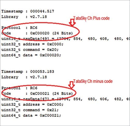
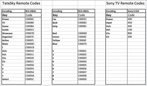
The lists of codes for TataSky set-top box and Sony TV used for the prototype are given in Fig. 9.
Building the IR-Blaster
The IR-Blaster part of Wi-Fi remote is built using another NodeMCU (Board2). The circuit diagram for the IR-Blaster is shown in Fig. 10. To give a stronger signal, the LEDs are driven by a 5V supply via two 2N2222 NPN transistors. The version shown has two IR LEDs (IRTX1 and IRTX2) to emit a very strong IR signal, though one IR LED is enough for a small room. The second IR LED should be added only if one IR LED is not enough.
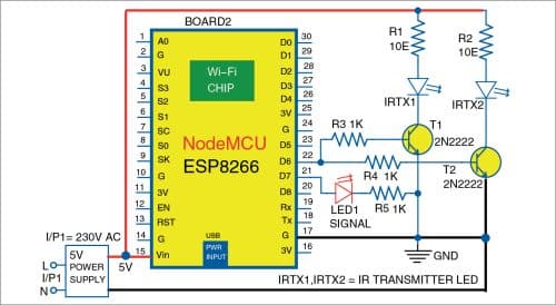
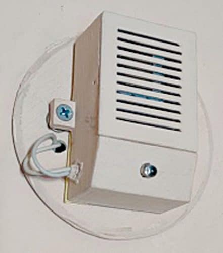
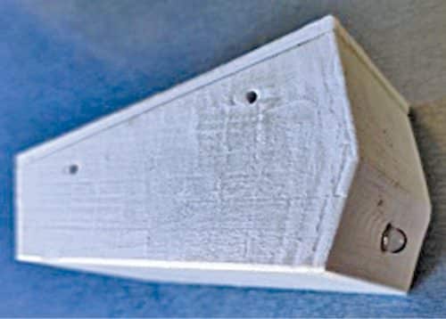
The IR-Blaster should be housed in a suitable enclosure and mounted on the wall opposite the place where the TV set and the set-top box have been placed. Please ensure that the IR beam has an unobstructed path to the TV and set-top boxes. If possible, one can use a 3D printer to print a suitable enclosure and mount it on a wall or room ceiling. The author’s prototypes are shown in Fig. 11 and Fig. 12.
Software
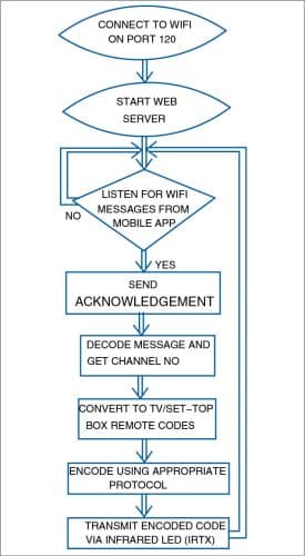
Download the Arduino sketch (WiFiRemoteVer1.4.ino) from the EFY website. Since the prototype has been built for a Sony TV with a TataSky set-top box, the program is written for this combination. Keeping this as a sample, you can rewrite the software for your particular brand of TV/set-top box and use the codes decoded discussed above. The flowchart for the sketch is shown in Fig. 13.
On boot-up, the NodeMCU connects to the home Wi-Fi network. You need to enter your Wi-Fi SSID and the corresponding password in the sketch. Since each time the IR-Blaster boots up the router may allocate a new IP address to it, it is better to have a known fixed IP address. The user may, depending on his router hardware, either reserve an IP address (using DHCP address reservation) or use the software method shown below.
The following values need to be defined in the sketch:
IPAddress staticIP(192, 168, 0, 51);
IPAddress gateway(192, 168, 0, 1);
IPAddress subnet (255, 255, 255, 0);
IPAddress dns(49, 205, 72, 130);
The staticIP address will be allotted to the NodeMCU. This IP address has to be one of the possible IP addresses within your internal network. Please also ensure that this address is not used by any other node on your network.
The gateway address is the IP address of your router. Here, the first three values of the router address are the same as the first three bytes of the IP address of the NodeMCU.
The subnet address is the subnet mask defined for your local network. The DNS address is the domain name server address and can be seen in your router internet settings. Since each router has different router administration screens, you have to either Google the details or consult your network provider for help.
If you find the above two options difficult, you may remove the above lines from the code. The router will then allocate an IP address of its choice to the NodeMCU/IR-Blaster, which may vary each time the NodeMCU boots up. In such a case, you will have to set up the new IP address in the Settings screen of your TVRemote mobile app explained above.
LED1 at pin D7 will light-up while the NodeMCU is connected to the network. After the Wi-Fi starts up, the NodeMCU will start the web server on port 120. The port number is an arbitrary number given to remove conflict with other programs using the standard http port 80. This completes the Setup( ) section of the sketch.
The loop( ) keeps listening to new incoming http (over Wi-Fi) messages from the mobile app. When it receives a message, it decodes it and extracts the channel number requested by the mobile app. To simplify the operation, only one type of message is sent.
Pseudo channel numbers have been assigned to operations like Power on/off, Volume plus/minus, etc. For a TataSky set-top box, channel numbers greater than 9000 have not been used; these free numbers have been assigned to such operations.
The incoming http message from the mobile is responded by the NodeMCU by sending a 200 response along with the channel number to the mobile app. The acknowledgement serves as a confirmation to the user that his request has been received by the IR-Blaster. If the mobile app fails to get this acknowledgement message within reasonable time, an error message showing ‘IR Blaster not connected’ is displayed on the mobile.
The sketch then checks whether the channel number received is within one of the following ranges:
- Between 0 and 9
- Between 100 and 8999
- Between 9001 and 9999
Single-digit channel numbers represent the digit keys that the user presses to type in any channel number. These keys are the equivalent of the number keys on your set-top box remote. IR code for each number pressed is transmitted in the sequence in which they are typed.
The second range (100 to 9000) represents the channel numbers assigned by TataSky to individual TV stations/channels. This feature is not available in the TataSky remote but has been built in this mobile Wi-Fi version. You can select any desired channel icon on the app and the set-top box will move to that channel. For example, on selecting DD News, the corresponding channel number 501 will be transmitted, and the user needs not press the 5, then 0, and then 1 key.
The third range (9001 to 9999) is used to signify special keys, like Volume plus, Volume minus buttons. The corresponding codes have been incorporated in the software (lines 103 to 140 of the sketch).
The IR message is encoded separately for the TataSky box (lines 222 to 220 of the sketch) and the TV (lines 229 to 232 of the sketch). Protocols of most of the common TV sets are built into the IRremoteESP8266 library, which we also used for decoding explained earlier.
The author’s prototype has been built for a Sony TV used in conjunction with a TataSky set-top box. Since readers may have a different brand of TV or set-top box, they need to modify the mobile app and the sketch to their particular brands using the author’s code as a sample. Main changes in the app that may need to be done are the channel numbers assigned to different channels (as per the set-top box) and the IR codes and protocols that need to be changed in the sketch.
Download Source Code
Ashok Baijal is a regular contributor to EFY, currently retired and working on home automation projects