


How does a colour e-Paper display (like red/black/white/yellow or red/black/white/grey) work without any backlight? Why do they consume so little power, and how do they sustain their image even after power is removed? These are natural questions when you see an e-Paper display showing crystal-clear content without being lit up!
Simply put, an e-Paper display contains millions of tiny microcapsules or microcups filled with charged particles of different colours—such as black, white, red, or yellow. When an electric field is applied, the particles move within the capsules, changing their position or orientation to reveal or hide specific colours on the surface.
In contrast, traditional displays like LCD, LED, or OLED rely on backlighting or side lighting. Their liquid crystals rotate or block light to control polarisation, and colour filters are used on top to produce full-colour images. All of this happens at a microscopic scale to generate bright, vivid visuals.

You could say that in an e-Paper, the image is created by reflecting external light, whereas in other displays, the image is created by emitting internal light. That’s why in a dark room, LCD/TFT/OLED displays glow visibly—they emit light. But an e-Paper display becomes invisible in darkness since it doesn’t emit light at all. This lack of a backlight is a key reason for their ultra-low power consumption.
What’s fascinating is that e-Paper displays retain their image even after power is cut off. That’s because the microcapsules don’t reset—they stay in their last electrically driven state. It’s like drawing on paper: once drawn, the image stays. It only becomes invisible when there’s no light to reflect off it.

Recommended: E-Paper Display Working Explained and What Are Its Advantages and Disadvantages?
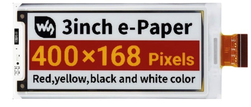
My four colour 400×168 Pixel Paper
Almost a year ago, I bought this four colour e-Paper display from Robu.in—practically at a throwaway price (INR 1150)!
The product page had a sample code to test the display, but it only worked with that fixed image. Despite several attempts, I couldn’t change the image or get anything else to work.
There seemed to be no proper library available to control this display, and it felt like just that one image enchanted the entire optics!
Recently, I discovered two updated libraries, and by combining them, it’s now possible to control the display & many other types of e-Paper displays in almost every way.
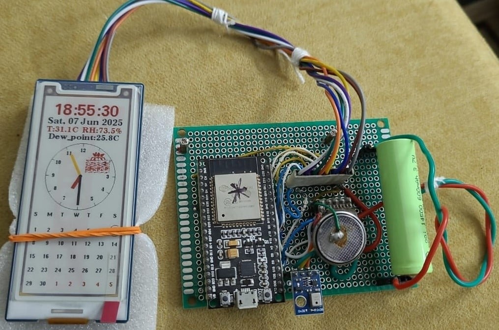
For graphical output, you’ll need to convert your image into a bitmap format before rendering it. In the code I’ve written, I created an analog-digital hybrid clock that also displays temperature, relative humidity, and dew point—thanks to an RTC (Real-Time Clock) and an AHT10 sensor.
As a playful touch, I also added a small raspberry image that randomly appears in different positions on the screen, filled with random colours—adding a bit of charm and life to the display.
Low-Power Operation
To run it on a battery, we have switched off all the unnecessary features of the ESP32. These codes are explained below.
WiFi.mode(WIFI_OFF); //As we are not using WiFi
btStop(); // disables Bluetooth
Serial.begin(115200);
delay(50); // small delay if needed
setCpuFrequencyMhz(40); // Reduce CPU frequency for low power consumption
Wire.begin(SDA_PIN, SCL_PIN);
Wire.setClock(100000); // Lower I2C clock speed for low power
Serial.end(); //May causes the switch on of the Onboard LED; if not, this will reduce power
//consumption further; just try & see
esp_sleep_enable_timer_wakeup(1 * 60 * 1000000); //Sleep for one minute
esp_sleep_pd_config(ESP_PD_DOMAIN_RTC_PERIPH, ESP_PD_OPTION_OFF);
// Turn off ADC & other RTC peripherals to further reduce power consumption
esp_deep_sleep_start();
} //setup ends.
Since we are using deep sleep, anything inside loop() will eventually be bypassed. However, before using deep sleep into your final code, you may check how your code works out inside loop() and that’s why if you bypass deep sleep code, your loop cycle will play out normally.
Prototype
How much Low Power
In the setup shown, I’m using a 3.7V 600 mAh Li-Ion battery. The device follows a sleep-wake cycle: it wakes up once every minute, updates the display, and then returns to deep sleep. During the active phase (about 3–4 seconds), the device draws around 6000–7000 µA, while in sleep mode, the current drops to 30 µA. Based on this duty cycle, the battery can easily last up to two months on a single charge! If you increase the time duration the battery life will increase further proportionately. Check the video here for power cycle consumptions.
BOM
- 400×168 3” 4-colour E-paper with HAT: ₹2331
- ESP32 – 01: ₹500
- AHT10 – 01: ₹100
- Regulator SL7533 – 01: ₹7
- DS3231: ₹150
- PCB, Li-Ion cell, Wirings – extra
Videos of the Project
Points to consider
Correct GPIO pin connections are critical for the display to work properly. While the I²C pins can be reassigned from the available GPIOs, the code must be updated accordingly. I’ve used only one side of the ESP32, so my pin selections reflect that constraint.
To help with GPIO configuration across different boards, the file GxEPD2_wiring_examples.h is included in the main code and provides reference pin mappings for a variety of supported boards.
Schematics
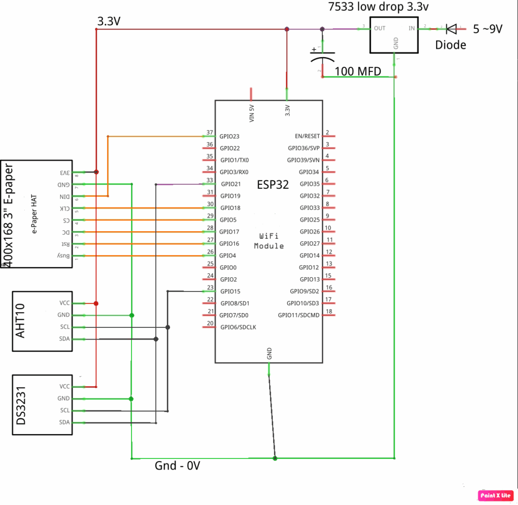
Since the device is a low-power 3.3 volt device and we intend to run it from a battery, we have used a low-dropout 3.3 volt regulator named 7533 instead of the popular 1117, which has a larger dropout voltage. The sensors are 3.3 volt low-power sensors.
Software
The libraries that are essential for this project are available in the links below.
Download these two zip files and then add them into your Arduino IDE [Sketch -> Add Library -> Add .zip Library… ]
Since they are big, they may not get installed into your …/library folder. In that case copy those .zip files into your ../library folder and then do the process again. If all fails just extract the .zip files and then copy those entire folders into the ../library folder.
Other essential libraries: RTClib.h and Adafruit_AHTX0.h may be installed using Sketch -> Add Library -> Manage Libraries…
After doing all these run this project sketch and it will run. The sketch consists of 4 files –
- GxEPD_wiring_examples.h – You will get board-specific wiring details
- GxEPD_selection_check.h – This is the E-paper-specific variables
- GxEPD2_display_selection_new_style.h – E-paper specific include files to process
- GxEPD2_U8G2_epaper.ino – Main project sketch file
All these files have been attached as a *.zip file.
Allied other uses of this project: Apart from the day-date-desk-calendar-temp-humidity display that we have done in this project, there are other potential uses possible on this project.
- Low power desktop weather station: Weather station with AHT10 / BME10 & icons of cloud, rain, sun, moon, phase etc. The weather report may be obtained using the Internet.
- A To-do reminder for your desktop: Display daily to-do list. The file may be fetched using email, Intranet etc. & displayed with an alarm sound. You may have to use an I2S amplifier for playing out sound.
- A Plant monitor / display: Will display moisture level, plant name, light exposure and watering reminder. Being an E-paper the battery life will be very long.
- A Visitor counter: Displaying occupancy before a meeting room lab entrance etc.
- A visitor batch: Showing name, Designation, purpose, room etc., showing the QR code.
- Supermarket tag or shelf level: Showing name, item code, rate, QR code etc.
Download Source Folder
Aftermath
E-paper is poised to become a mainstream display technology in the coming decade due to its ultra-low power consumption and excellent sunlight readability. While its refresh rate currently lags behind LCDs or OLEDs, advancements are steadily closing this gap. The arrival of 7-colour E-paper marks a significant leap toward more vivid and informative visuals. With evolving controller support and better libraries, DIY and commercial adoption is bound to grow. This project is just a small glimpse into that promising future.
Related articles:
Wi-Fi Enabled E-Paper Display Reference Design
Personalized E-Paper Clock Using ESP32 Microcontroller
Batteryless E-paper Display Project
