


 Sockets, boards and wires generally receive a limited supply of electric current. Any ‘current overdraw’ from them via thin wiring can result in a short circuit. Therefore, real-time power usage monitoring for each socket is required to identify the appliances that consume more power and judiciously use electricity, thus efficiently managing household electricity bills.
In today’s IoT project, you will learn to make an IoT-based current monitoring device that can detect current overdraw and automatically turn off the circuit. It can also give real-time data regarding power usage over a WiFi connection or a webpage. So let’s start building the project by collecting the following components.
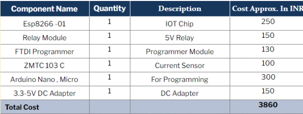
Bill Of Materials

Coding
Add the Esp8266 board to Arduino IDE. To do so, follow the instructions given in this article. Next, install the libraries EmonLib for measuring the current from the ZMTC103C current sensor and ESPDash that will show the graph/data for electric current and power usage. Since the ESP8266-01 module does not have an analogue pin, use the Arduino board and ESP8266 together to get current and display over WiFi on the web dashboard. Now write the code for Arduino that will check the amount of electric current and automatically break the circuit when a current overdraw is detected.
NOTE: If you prefer to instead use any other ESP8266 board like the node MCU that has analogue pins, then you can remove the Arduino board and make a few changes in the code.
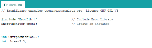
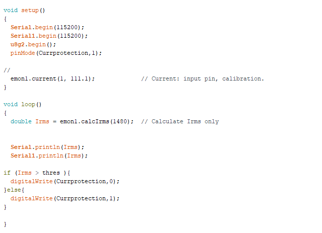
Arduino Code
Include the EmonLib library and then define the relay pin for breaking the circuit. Next, create a variable for storing the threshold current value so that the circuit automatically breaks if the electric current drawn becomes higher than the threshold value. Now, create the setup function and set the serial baud rate to 115200. Create a loop function for checking the electric current reading. Make sure to pass the value over to the serial to view the statistics regarding the current usage on the web dashboard.
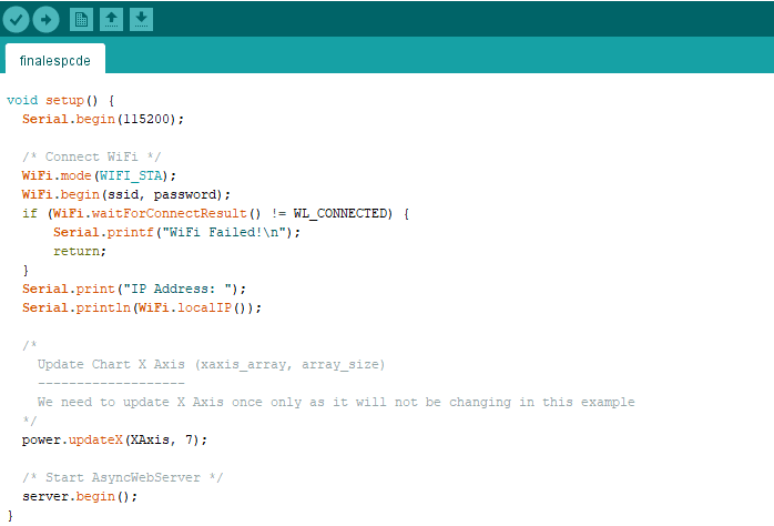
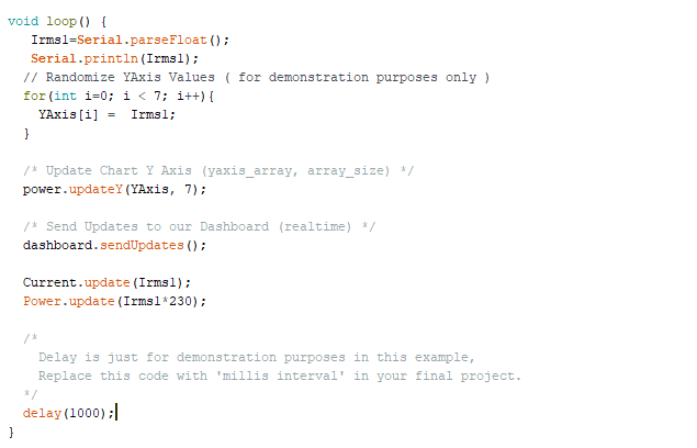
IoT Energy Meter Code
Now create a code for the ESP8266-01 to display the energy data consumed by electrical appliances. Use the ESP Dash library for creating graphs and adding cards to the display data and updating them in real-time.

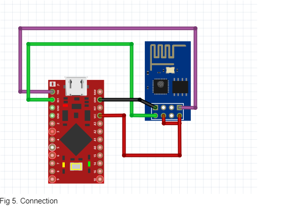
Connection
After uploading the codes to the Arduino board and ESP8266-01, connect the components as shown in the circuit diagram. Connect one pin of the ZMTC sensor to the GND pin of Arduino and another to the analogue pin A1 of Arduino.
For connections between the relay module and the Arduino board, refer to the below table:
| Relay | Arduino |
| VCC | 5V DC |
| GND | GND |
| IN1 | PIN 9 |
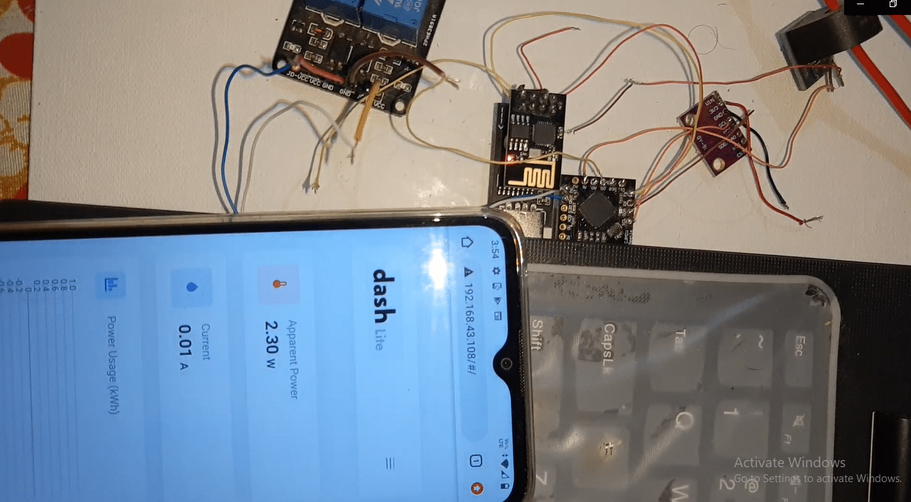
Testing
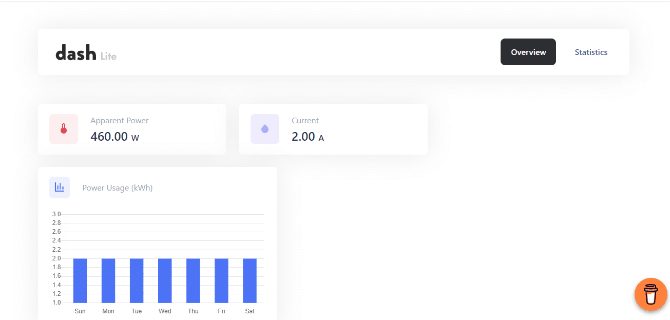
Power the module and connect any AC appliance that consumes current more than the threshold value. On detecting this, the relay module should automatically break the circuit. To view the energy meter and monitor the current sent by the AC appliances, connect the WiFi of your home router/hotspot to the WiFi network connected with the ESP8266. Now open the IP address on a search engine to view the power consumption dashboard.

Sir,
Thank you for the useful project. As per
Bill Of Materials the cost of the project is
250+150+130+100+300+150 = ₹1080
But the total cost is mentioned as ₹3860
Either some of the items were missed or the total is incorrect.