


Cathode Ray Oscilloscopes are vital instruments in the field of electronics, playing a pivotal role in the design, development, and troubleshooting of electronic circuits and systems.
These versatile tools have revolutionized the way engineers and technicians visualize electric signals.

Table of Contents
Since its invention in 1897, the cathode ray oscilloscope (CRO) has come a long way in detecting the presence of electrons. A CRO is an electronic test instrument that is used to
- Visualize electric signals
- Measure signal characteristics (Voltage, time, frequency)
- Analyze signal behaviour
Have you ever come across difficulties like limited bandwidth and resolution hindering accurate high-frequency signal measurements? Lack of storage capability to analyze complex waveforms? Or is manual signal triggering slowing down your work?
That is where the Cathode Ray Oscilloscope comes in as a game-changing tool designed to overcome these limitations.

It is an integral part of modern-day oscilloscopes used for measuring various waveforms of electrical circuits. An X-Y plotter plots an input signal against another signal or against time, enabling the study of waveforms, transients, and time-based or frequency-based analysis.
A CRO is a complex device consisting of many parts and components. In this article, we’ll delve into the detailed working of a CRO, Types of CROs, applications of CROs, and modern alternatives to CROs.
Therefore, before going in-depth into it, let’s first understand the fundamental concept behind a Cathode Ray Tube (CRT), the working of CRT and its applications.
Cathode Ray Tube (CRT)
A CRT is a vacuum tube that acts as the main part through which the functionalities of a CRO are carried out.
CRT is a type of display technology that uses electrons to produce images on the screen as visual waveforms.
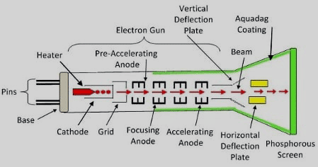
Construction and Components of CRT
- Heater: This part is responsible for heating the cathode.
- Cathode: On being sufficiently heated, electrons are emitted from the cathode. To achieve this, a layer of barium oxide is coated on one end of the cathode.
- Grid: It is kept at a negative potential and helps control the intensity of the electron beam moving towards the anode. The entire structure is made from nickel.
- Pre-accelerating anode: Provides acceleration to the anode before entering the Focusing Anode.
- Focusing Anode: It helps align the incoming electron beam.
- Accelerating anode: Its job is to again accelerate the newly aligned electron beam. Note here that both pre-accelerating and accelerating anodes are connected to a common positive potential of 1500 volts.
All these components collectively form the electron gun.
Working of CRT
Putting it all together, in a Cathode Ray Tube (CRT), an electron gun shoots a stream of electrons, which are sped up and focused into a thin beam by high-voltage anodes. This beam is aimed at a screen coated with phosphor. When the electrons hit the screen, the phosphor lights up, creating the display.
The position of the beam is controlled by deflection plates. By applying voltages, the plates move the beam up, down, left, or right, allowing it to reach any point on the screen. The phosphor’s glow lasts long enough to create smooth images as the beam moves.
This combination of electron control and precise positioning is what makes CRTs work in devices like oscilloscopes and old-style displays. Check out this short video that animates the working of CRT
Applications of CRTs
- TVs & Monitors: CRTs are used to display video and image content, providing visual information
- Radar Systems: CRTs display radar signals, helping navigate aircraft, ships, etc. They are also used for weather monitoring.
- Medical Equipment: CRTs help display medical images such as X-rays to help in diagnosis.
- Scientific Instruments: CRTs are used in instruments like spectroscopes, chromatographs, and various other instruments
- Oscilloscopes: CRTs can be very helpful in analyzing waveforms from electric signals
Now that we have explored the fundamentals of Cathode Ray Tubes, the core technology driving Cathode Ray Oscilloscopes, let us delve into the essentials of CROs.
Understanding CRO basics will enable you to troubleshoot electrical circuits, analyze waveforms, measure the parameters of a signal, and optimize the electronic system performance.
Cathode Ray Oscilloscope (CRO)
As mentioned, a CRO is a device that is used for measuring and displaying different forms of electrical signals.
While a CRT is a type of display technology, it is functioning as a display tube for the CRO.
Cathode Ray Oscilloscope is an electronic test instrument that can be found as a key player in the electrical, medical, industrial automation, and communication technology.
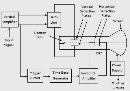
Construction and Components of CRO
- Cathode Ray Tube: Through this mechanism, electrons are emitted and controlled to form the desired signal image on the fluorescent screen.
- Vertical Amplifier: This amplifies the input signal for display on the CRT screen.
- Delay Line: It provides a certain signal delay that is applied to vertical deflection plates of CRT.
- Trigger Circuit: It produces a triggering signal for synchronizing both horizontal and vertical deflections of the electron beam.
- Time base Generator: It produces a sawtooth signal for horizontal deflection of the electron beam.
- Horizontal Amplifier: It amplifies the sawtooth signal and then connects it to the horizontal deflection plates of CRT.
- Power supply: It produces both high and low voltages. The negative high voltage and positive low voltage are applied to CRT and other circuits respectively.
Through this procedure, a CRO displays the applied input signal on the screen of the CRT, providing signals in the time domain.
Working of CRO
After when the CRT generates electronic beams that illuminate the screen, then there is a need to translate these actions into meaningful actions.
We have already discussed the function of the vertical deflection plates, that is, to move the beam up and down based on the input signal’s amplitude. This creates the Y-axis of the waveform. Meanwhile, the horizontal deflection plates shift the beam left and right, forming the X-axis, with their movement controlled by the time base generator for a steady sweep across the screen.
To keep the waveform stable, the CRO uses a triggering mechanism that syncs the horizontal sweep with a specific point in the signal, ensuring a consistent trace rather than a jumping image.
With the waveform displayed, users can easily analyze:
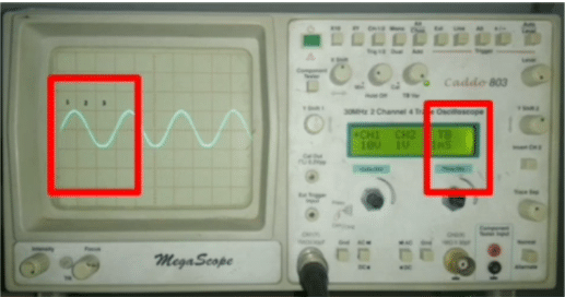
- Amplitude: Height indicates voltage level. Use the volt/division setting to determine the sensitivity. Measure the distance from the baseline to the waveform peak.
Then calculate the amplitude using the formula:
| Amplitude = Number of Vertical Divisions * Reading on Volts/Division Knob |
The number of Vertical Divisions simply means the number of squares on the CRO screen in the vertical direction.
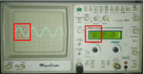
In this case,
- The number of Vertical divisions = 2
- Reading on Volt/Division = 10V.
So,
The value of amplitude = 2*10V = 20V
- Time Period: The time taken for one complete cycle of a waveform is known as the time period or time duration. By adjusting the time/division knob on the CRO, we can change the number of divisions of the signal horizontally.
| Time Period = Number of Horizontal Divisions * Reading on the Time/Division Knob |
The number of Horizontal Divisions simply means the number of squares on the CRO screen in the horizontal direction.
In this case,
- Number of Horizontal Divisions = 3
- Reading on the Time/Division = 1ms
So,
The Time Period = 3*1ms = 3ms
- Frequency: Distance between cycles shows frequency. It is the inverse of time period
| Frequency = 1/Time Period |
Using the previous example, where Time Period = 3ms,
Frequency = 1/3 = 333.3333 Hz
The shape of the waveform also provides insights:
- A sinusoidal waveform indicates AC signals.
- A square waveform represents digital signals.
- Complex waveforms may reveal mixed signals or transient behaviours.
CRO Modes of Operation
There are various modes of operation present in CRO. The modes differ from one model to another model of CRO. But given below are some of the common modes of operations present in CROs.
- Y-T mode: Most common mode, the Y axis represents voltage, and the X axis displays the time.
- X-Y mode: Displays one signal as a function of another signal. It basically displays the Lissajous patterns
- Dual-Trace mode: Displays two signals simultaneously
- Sweep mode: Displays time-varying signals
Types of CRO
There are various types of CROs available; some common CROs include:
- Analog CRO: Uses analog circuits to display waveforms
- Digital Storage CRO: Converts analog to digital data and analyzes waveforms using digital signal processing.
- Mixed Signal CRO: Combines both analog and digital channels simultaneously and analyzes the waveforms.
Advantages and Disadvantages of CRO
| Advantage | Disadvantage |
| Real-Time waveform display | Costly |
| High-Bandwidth | Less portable due to their heavy weight |
| Multiple signal analysis | Limited data storage |
| Can be used for various applications including audio and radio frequency analysis | Difficulty to repair |
| Triggering capability | Prone to drift errors, regular calibration required |
Applications of CRO
While numerous, a CRO can be used for the following purposes:
- To determine the amplitude of a waveform.
- Comparison between the phases and frequencies of electrical signals.
- Help measure capacitance and inductance values.
- In communication systems, CROs analyze the signal modulation, demodulation, and transmission. They also help in measuring SNR and distortion.
- In the medical field and medical trials, it can be used for monitoring various body parameters like heartbeat rates and nervous reactions.
Also Check: Vibration Activated Smart CRO Probe
Troubleshooting Common Errors
| Problems | Solutions |
| Excessive Noise in the Waveform | Use proper grounding techniques to reduce noise. Adjust the time base settings for better signal resolution. Apply filters to the input signal if necessary. |
| Input Signal Not Triggering | Adjust the trigger level and coupling settings (AC or DC). Ensure the input signal is within the trigger threshold. Check the trigger source settings; make sure the correct channel is selected. |
| Waveform is Distorted | Check for incorrect vertical sensitivity settings and check for interference from nearby devices. Ensure the probe is properly connected. |
| Phosphor Burn-in | Reduce brightness settings to prevent prolonged exposure. Utilize screensavers if available. Else replace the screen |
People Also Ask
What is the typical lifespan of a CRO’s CRT?
The lifespan of a CRT can vary, but it typically lasts several years with proper usage; however, the phosphor coating may degrade over time, leading to diminished brightness.
Can we connect CRO to the computer?
Traditional CROs are standalone devices, so one cannot connect to the computer. However, modern CROs can be interfaced with computers using ethernet or USB.
What is the purpose of triggering CROs?
By using a trigger, one can stabilize the waveform by stabilizing the horizontal sweep with a specific point in the input signal.
What are the key features to look for in a CRO?
Look for Important features such as bandwidth, sample rate, triggering capabilities, vertical and horizontal sensitivity, and the number of channels based on the application.
What is the role of the time base in a CRO?
The time base is used to control the horizontal sweep rate, allowing the waveform to be displayed in relation to time on the X-axis.
To read other interesting Electronics basics articles: click here
