


Now the pandemic COVID 19 caused by Corona virus is spreading fast throughout the world. The Corona virus has taken up mutation and the second wave is spreading along various countries around the world. Nearly 148.52 Million people around the world are infected and around 3.134 Million people are reported dead by this corona virus infection. Vaccines to fight COVID 19 have now arrived in the pharmacies. Vaccines alone do NOT give 100 % protection for life from Corona virus.
It is also reported that most of them who are infected with Corona virus experience shortness of breath in addition to body temperature, cough and die due to breathing difficulties. Hospitals in India do not have enough oxygen cylinders and ventilators to pump oxygen to aid respiration for these Corona patients. This has resulted in the death of so many patients suffering from COVID 19. While vaccines for COVID 19 are available, the presently available method to save the life of newly infected COVID 19 patients is to supply oxygen cylinders and low cost ventilators to the hospitals.
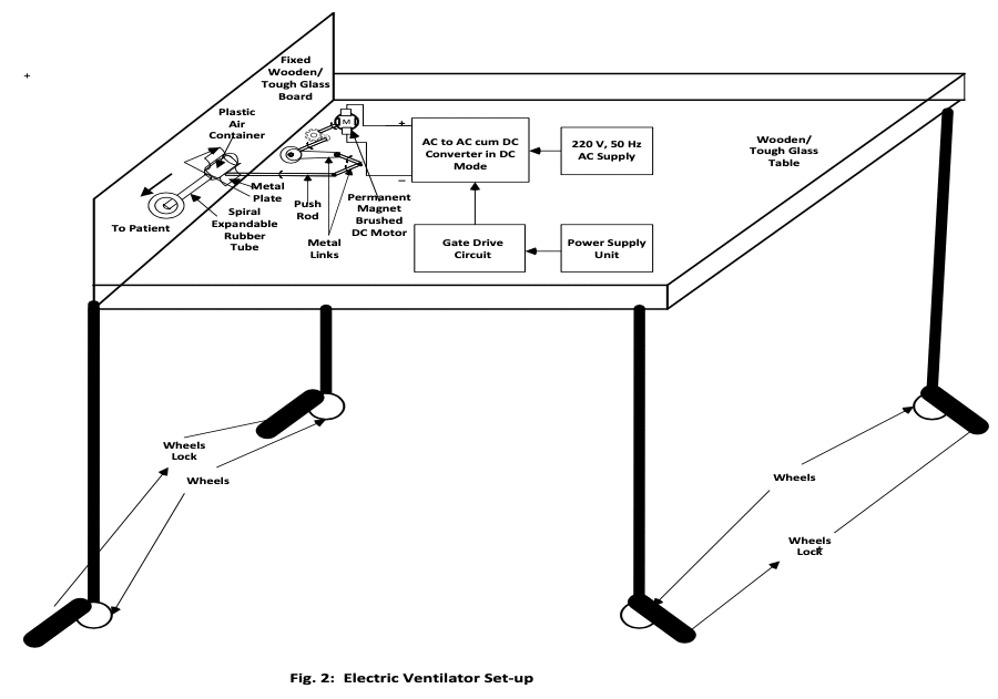
With this point in mind, Myna Electrical and Electronics Consultancy has developed one electric ventilator. This ventilator can be used for COVID 19 and other patients having breathing difficulties. The model of this electric ventilator was tested using software in the personal computer. Model simulation results are successful. The model is developed using an AC to AC cum DC power electronic converter, operated in the DC mode. The input is the 220 V, 50 Hz AC supply. This is stepped down to a suitable magnitude (24 V, 50 Hz, AC) and given to a pair of IGBT bidirectional switches, operated in the DC mode. To the output of the power electronic converter, a low pass filter and a potential divider to adjust the applied voltage are connected. The output of this potential divider is connected to the armature of a Permanent Magnet DC (PMDC) Motor. Two modes of operation of this PMDC are possible. In the first mode, the DC is supplied with positive polarity to one terminal of armature and the other negative terminal is grounded. After a specified period of time, this applied voltage polarity to armature terminals are reversed so that PMDC motor starts rotating in the opposite direction. In the second mode, the applied DC voltage polarity is maintained the same throughout so that PMDC motor runs in one direction only. A gear train and rotating disc connected to the PMDC motor shaft with metallic links and push rod provide a crank shaft motion as in a steam engine to press and release the plastic container to supply oxygen to the patient. The length of these metallic links and push rod have to be adjusted to the table size where this electric ventilator is placed, to provide desired performance.

Electric Ventilator
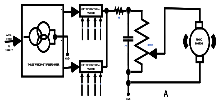
The proposed electric ventilator block diagrams are shown in Fig. 1 (A), (B) and (C) and their set up is shown in Fig. 2. Referring to Fig. 1(A), 220 V, 50 Hz AC supply is given to the primary of the three winding transformer. The two secondary winding output voltages are given to a pair of IGBT bidirectional switches and the other two ends of the secondary windings are connected together to ground. The output terminals of the two bidirectional switches are tied together and this is connected to low pass filter (RF, CF) and then to a potential divider (RPOT). The variable terminal of RPOT is connected to the positive terminal of PMDC motor and the negative terminal is grounded.
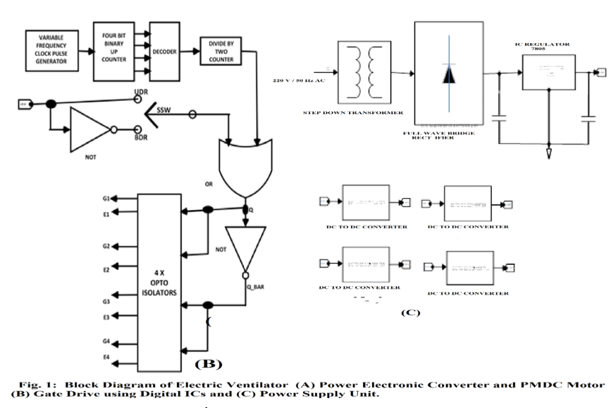
The gate drive circuit is shown in Fig. 1(B). Here a variable frequency clock pulse output is driving a four bit binary up counter. A specified value of this counter output is then decoded using logic gates and this square pulse output is given as clock input to a divide by two counter. The output of this divide by two counter is given to one input of an OR gate and the other input to OR gate is from a selector switch SSW. A +5 V power supply and its inverted output using NOT gate form the two inputs to SSW. Selecting +5 V or UDR input using SSW causes the output Q of OR gate to remain HIGH (+5 V) always ensuring unidirectional rotation for the PMDC motor. If SSW is thrown to BDR position, Q output of OR gate takes both HIGH and LOW (0 V) causing two way or bidirectional motion to PMDC motor. This Q output of OR gate is inverted using NOT gate giving Q_BAR output. This Q and Q_BAR outputs are given to four opto isolators which form the gate drive for the pair of bidirectional switches in Fig. 1(A).
The power supply unit is shown in Fig. 1( C ). Here 220 V, 50 Hz AC supply is given to a step down transformer which gives 9 V, 50 Hz AC output voltage. This secondary output voltage of transformer is then rectified using a full wave diode bridge rectifier, filtered and given as input to an IC voltage regulator 7805. The +5 V output of IC regulator forms the power supply to digital ICs in Fig. 1 (B). This 5 V output of IC 7805 is also given to four DC to DC converters each of which give output of +15 V for the opto isolator power supply in Fig. 1(B).
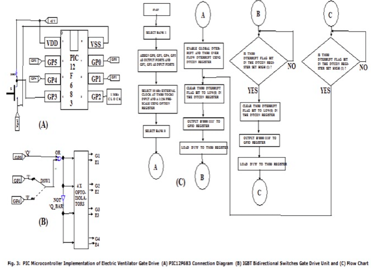
The gate drive can also be developed using embedded microcontroller. The PIC12F683 microcontroller schematic, gate drive connection diagram and flow chart for the implementation of the gate drive for the IGBT bidirectional switch pair are shown in Figs. 3(A), 3(B) and 3(C). Here referring to Fig. 3(A), GP0, GP1 and GP4 are used as output ports. Ports GP2 and GP3 are input ports. A 10 kHz clock is connected to GP2 port which forms the TOCKI input. A prescale of 1:256 for the clock is chosen using OPTION register. Port GP0 gives 0.25 Hz clock output with equal on and off time. Port GP1 always output logic HIGH (+5 V) and GP4 always output logic LOW (0 V). Gate drive connection is shown in Fig. 3(B). Output of ports GP1 and GP4 are given to SPDT switch marked DSW1. Output Q of GP0 port and that of SPDT DSW1 are given to a two input OR gate. The output of the OR gate and the inverted output using NOT gate are given to four opto isolators which form the gate drive for the pair of IGBT bidirectional switches in Fig. 1(A). When DSW1 is thrown to GP1 port, output Q of OR gate is always HIGH, Q_BAR is always LOW and the PMDC motor rotates only in one direction. When DSW1 is thrown to GP4 port, Q takes both HIGH and LOW value and Q_BAR takes LOW and HIGH values with a time interval of 2 Seconds and the PMDC motor rotates in both direction due to reversal of voltage polarity at the armature terminals. The flowchart for PIC12F683 implementation to generate 0.25 Hz square wave at the GP0 port is shown in Fig. 3(C). To generate on and off delay each of 2 Seconds, a pre-calculated digit (178) is uploaded TMR0 register, GP0 is set HIGH and TMR0 is allowed to count up. As the TMR0 register overflows, the TMRO interrupt flag is cleared, GP0 is reset to LOW and uploading the above pre-calculated digit to TMR0 register and allowing it to count up until overflow occurs, the time delay process is repeated and port GP0 output is a 0.25 Hz square pulse.
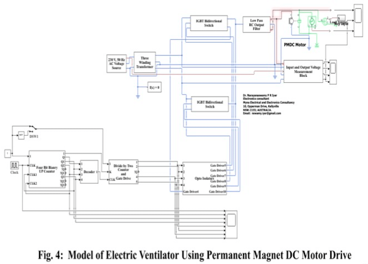
The model of the electric ventilator shown in Fig. 1 (A) to (C) is shown in Fig. 4 above. In Fig. 4, the potential divider RPOT is eliminated so that full rated voltage is applied across the armature terminals of the PMDC motor. In Fig. 2, gear train, disc, mechanical links and push rod are attached. Although this contributes to some load to the PMDC motor, this load is neglected and a zero external load is applied. Simulation of the model in Fig. 4 was carried out with zero external load for both unidirectional and bidirectional rotation of the PMDC motor. This is presented in the next section.
Simulation Results
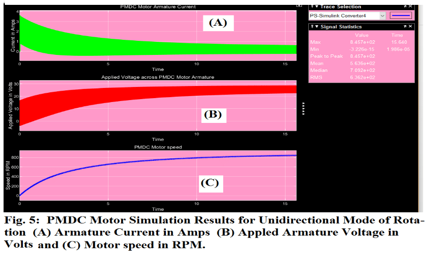
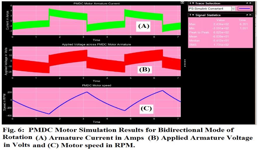
In Fig. 4, switch DSW1 was first thrown to +5 V (logic 1) position for unidirectional rotation of PMDC motor and with rated voltage applied to armature terminals, simulation was carried out and the results are shown in Fig. 5 (A), (B) and (C). With switch DSW1 in zero volts (logic 0) position for bidirectional operation of the PMDC motor, simulation was carried out and the results are shown in Fig. 6(A), (B) and (C).
Discussion of Results
The AC to AC cum DC converter is my patent [1]. From Fig. 5, it is seen that with rated DC voltage applied across the armature, the speed of PMDC motor continues to rotate only in one direction and reaches 800 RPM. No load is applied and the steady-state armature current is well below the rated value. From Fig. 6 it is seen that with rated voltage applied across the armature, the PMDC motor rotates in both directions reaching +200 and -200 RPM respectively. In both cases speed reduction gears with a ratio of 1:200 or higher have to be used. Also with potential divider RPOT, it is possible to apply voltage to motor armature starting from minimum value and gradually increasing until desired speed and performance is achieved. The arm coupled to the shaft of the motor through gear train moves forward and backwards pushing and releasing the plastic air container pumping oxygen to patient. The speed and time duration of pushing and releasing the plastic air container can be varied by varying the clock frequency. The length of this push rod, clock frequency, gear ratio and the applied voltage across motor armature can be decided only after mechanical set up on a table.
Conclusions
A novel method of developing an electric ventilator using my patent AC to AC cum DC converter operated in the DC mode along with a PMDC motor is presented with simulation results. Simulation results show that with proper DC voltage applied across motor armature using potential divider, using suitalble speed gear ratio and by varying the clock frequency it is possible to achieve desired performance both in the unidirectional and bidirectional mode of rotation of PMDC motor.
By Dr. Narayanaswamy P R Iyer, Founder and Electronics Consultant Myna Electrical and Electronics Consultancy
Reference:
[1] Narayanaswamy P R Iyer: “A Single Phase AC to PWM Single Phase AC and DC Converter” (Alternative title: Swamy Converter”), Patent, Faculty of Engineering, The University of Nottingham, Nottingham, UK, November 2013.

good