Artificial intelligence for gesture recognition and classification has transformative potential across industries, from healthcare to manufacturing and consumer devices. It enables tasks like motion tracking in smartwatches, anomaly detection in machinery, and vehicle predictive analysis.
Implementing AI on compact devices like the IndusBoard Coin—a 3cm innovation with built-in sensors—demonstrates how these capabilities can be brought to edge devices with limited resources.
| Bill of Materials | |
| Components | Quantity |
| IndusBoard Coin | 1 |
| USB C-type cable | 1 |
We create a simple model for gesture detection, designed to classify motions commonly used in smartwatches, phones, and exercise-related devices. The model is optimised to run efficiently on a microcontroller (MCU), overcoming constraints like limited RAM and storage while delivering reliable AI performance.

POC Video Tutorial
Only a few components, detailed in the accompanying table, are needed to build the device. Fig. 1 shows the prototype testing setup, showcasing how AI can seamlessly execute tasks on the edge.
An online tool named Edge Impulse was used to collect the data, train a machine-learning model, and deploy it on the IndusBoard MCU. An Edge Impulse account must be created using this link. The developer and student mode offers a free account, while the enterprise version is available for factories or industrial use.
After creating an Edge Impulse account, the Edge Impulse Data Forwarder must be installed on the PC. For macOS, Linux, or Windows, the installation can be completed using the terminal (cmd for Windows) by running the following commands sequentially:
- Installing Node.js:
node -v
npm -v
- Installing Edge Impulse CLI:
npm install -g edge-impulse-cli
- Setting up the Data Forwarder:
edge-impulse-data-forwarder
Connecting IndusBoard Coin to Edge Impulse
The IndusBoard Coin must be connected to Edge Impulse to collect sensor data. The data forwarder code is required for this purpose.
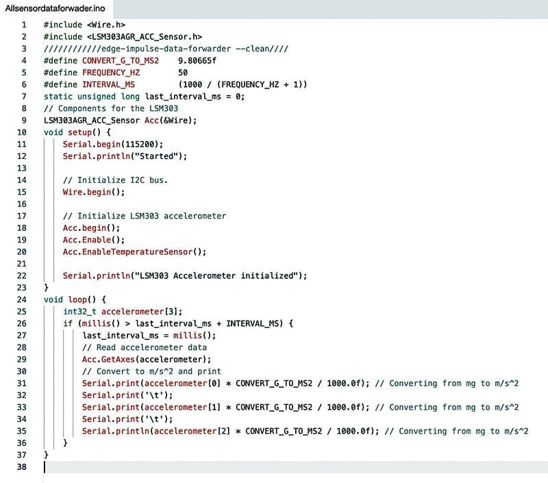
The code must be modified to extract data from the relevant sensor for other sensors like light, environment, air quality, or similar. In the loop, sensor data can be sent to the serial port. For multiple sensor values, each can be separated using:
Serial.print(‘\t’);For example, accelerometer data with three values (x, y, z axis) can be separated after each axis data using:
Serial.print(‘\t’);The data forwarder code should be prepared and modified according to the requirements. The code can be downloaded from electronicsforu.com. Detailed guidance on the data forwarder code is available at Edge Impulse CLI – Data Forwarder. Fig. 2 shows the Edge Impulse data forwarder code.
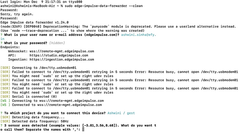
After uploading the data forwarder code and the IndusBoard to your laptop’s USB port, open the terminal for Linux or macOS (Cmd for Windows), then run the following command. For macOS and Linux, you might need to use sudo for superuser access, but it is not needed for Windows:
edge-impulse-data-forwarder --cleanThen, the system prompts the email ID to log in, followed by a request for the password. A list of models associated with the account is displayed, allowing the selection of the desired model to connect to.
The process involves detecting the computer’s hardware. If successful, the system automatically connects. If not, a list of available ports is displayed, prompting the selection of the correct one.
Next, the system detects sensor values from the IndusBoard. If multiple values exist, the system requests their names, separated by commas. For instance, the ACC sensor provides three-axis values. Input “x, y, z” in the terminal (see Fig. 3). Fig. 3 shows Edge Impulse connecting with IndusBoard using the data forwarder in the terminal.
Collecting Dataset
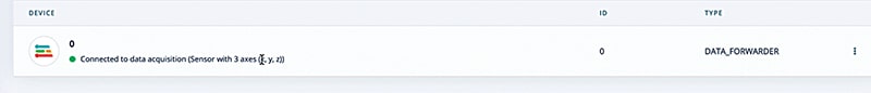
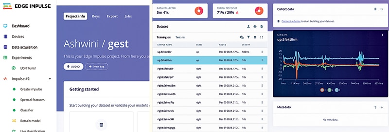
Now, in the terminal, either follow the provided link to open the dataset sample or navigate to the model in the devices section, where the IndusBoard will appear.
Then, go to the data acquisition section to collect the dataset. Click ‘Start Sampling,’ perform the gesture, assign the appropriate label, and collect the test and training data.
Fig. 4 shows the device connection status in Edge Impulse. Fig. 5 shows the dataset collection.
Impulse Design
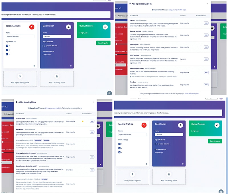
Design the impulse according to the requirements. Here, there is an option to choose whether it’s a model for a single sensor value, sound data spectrogram, temperature sensor, image data, or multi-axis value. The multi-axis value, which is the spectral data, is used in this case.
Next, select the learning block. Here, an option exists to choose how the ML model should be learned. It can predict, find the analogy, or classify. Depending on the design requirements, select either the classification or prediction option. Fig. 6 shows the impulse design.
Training and Testing ML Model for Gesture Recognition
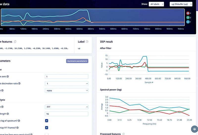
Go to the ‘Generate Features’ option and generate the features for the sensor data. After generating the features, save the generated data. The sensor graph can also be trimmed to extract features from the main point where the graph changes due to motion and gestures.
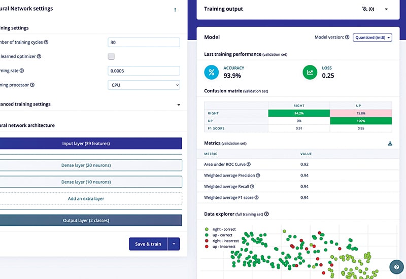
Next, move to the ‘Classifier’ section and select the neural layer, the number of training cycles, and the model type (SSD MobileNet or another). The default settings have been used, but they can be customised if preferred.
Then, click ‘Save and Train’ to initiate the ML model training. After training, the model will display its learning progress in a graph. If satisfied with the accuracy, proceed to test the model’s performance. Fig. 7 shows the trained ML model.
Next, proceed to test the ML model. Subsequently, click on ‘Classify All’ to classify all the data and obtain the results. The model is considered decent if the accuracy is greater than 70%.
However, if the results are unsatisfactory, increase the accuracy by adjusting the accuracy threshold. Alternatively, select the ‘Retrain Model’ option to tweak the training cycle and retrain the model. Fig. 8 shows the accuracy of the trained ML model.
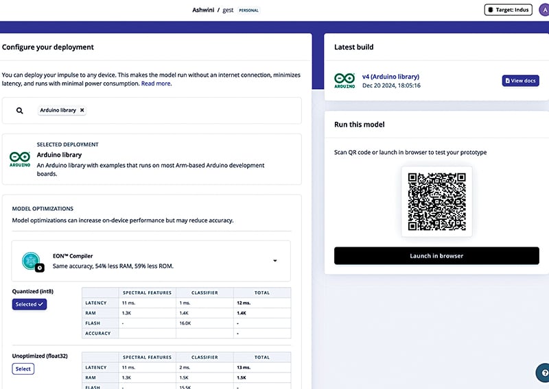
Deployment
Go to the deployment section here. Select the MCU and chips for deployment. The IndusBoard, programmed in Arduino IDE, is used in this case. The Arduino library is selected.
After that, select the ‘Build’ option, build the library, and automatically download the Arduino library to the laptop. If there is a need to tune and optimise the ML model, the EON tuner can be used; however, in this case, the model is used without tuning.
Next, open the Arduino IDE, go to ‘Sketch’→’Include Library’→’Add Zip Library’ and select the library just downloaded to add it. Next, go to the ‘Library Examples’ folder, then the ‘ESP32’ folder.
Then, go to ‘sensor inference’ and open the example for the continuous sensor. The code can be modified to use the sensor and enable predictions based on the sensor data. The LSM303 sensor is used here, so the example code is modified accordingly. The library and code can be downloaded from electronicsforu.com.
Next, select the IndusBoard chip, specifically the ESP32-S2 Dev module, and upload the code. The compilation process takes over two minutes because the entire ML model is compiled and converted to binary format.
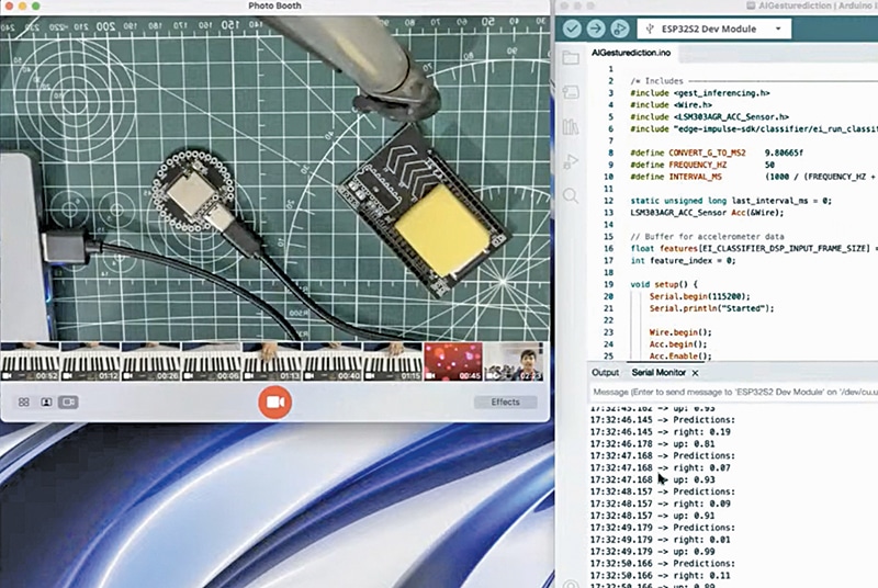
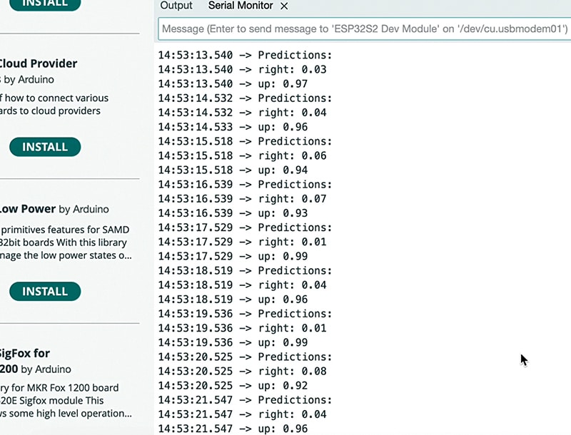
Therefore, there will be a delay after uploading the code. Open the serial monitor and set the prediction for gesture performance. Perform the gesture; the device will detect it and display the results. Subsequently, create a function that executes specific actions when a particular gesture is detected.
This function can then perform various tasks based on the gesture. Fig. 9 shows exporting the Arduino IDE library, while Fig. 10 shows the AI predicting the gesture.
Bonus: You can watch the step-by-step video tutorial of this DIY project
Ashwini Kumar Sinha, an IoT and AI enthusiast, is a Tech Journalist at EFY.