Antenna polarisation (or polarization) is a very important consideration when choosing and installing an antenna and can mean as much as a 20db in signal loss if the receiver and transmitter antenna are not using the same polarisation. Most systems use either vertical, horizontal or circular polarisation.
Basic Field Equations
Suppose an electromagnetic wave, radiated by an antenna, has an electric field E ( a vector) with two components: E x and E y.
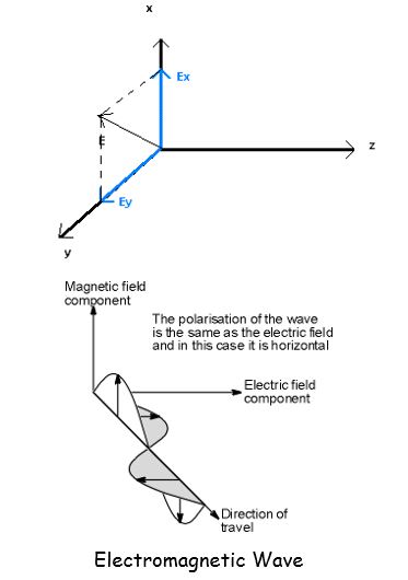
Let us assume that the components E x and E y of electric field E are given by
where a is the amplitude of component E x and b is the amplitude of component E. Phi is the difference of phase between the two components.
Polarisation
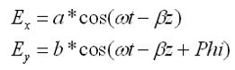
An antenna is a transducer that converts radio frequency electric current to electromagnetic waves that are then radiated into space. The electric field plane determines the polarisation or orientation of the radio wave. In general, most antennas radiate either linear or circular polarised.
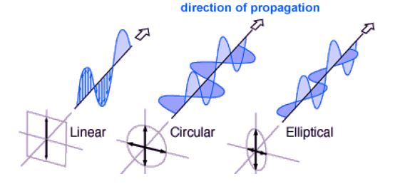
A linear polarised antenna radiates wholly in one plane containing the direction of propagation. Where a circular polarised antenna, the plane of polarisation rotates in a circle making one complete revolution during one period of the wave. If the rotation is clockwise looking in the direction of propagation, the sense is called right-hand-circular (RHC). If the rotation is counter clockwise, the sense is called left-hand-circular (LHC).
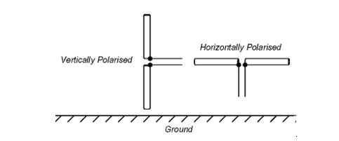
An antenna is said to be vertically polarised (linear) when its electric field is perpendicular to the Earth’s surface. An example of a vertical antenna is a broadcast tower for AM radio or the “whip” antenna on an auto-mobile. Horizontally polarised (linear) antennas have their electric field parallel to the Earth’s surface. Television transmissions use horizontal polarisation
Circular polarised wave radiates energy in both the horizontal and vertical planes and all planes in between. The difference, if any, between the maximum and the minimum peaks as the antenna is rotated through all angles, is called the axial ratio or elliptically and is usually specified in decibels (dB). If the axial ratio is near 0 dB, the antenna is said to be circular polarised, when using a Helix Antenna. If the axial ratio is greater than 1-2 dB, the polarisation is often referred to as elliptical, when using a crossed Yagi.
What polarization is required?
Most communication systems use either vertical, horizontal or elliptical (RHC-right hand circular or LHC-left hand circular) polarization, with vertical dominating commercial VHF/UHF applications. In some instances, the selection is determined by the installation site, with the antenna oriented to provide the best performance. If this is anticipated, your antenna should provide mounting for either polarization.
Selecting the proper polarization for the system can enhance the overall performance by minimizing the interference from adjoining systems. For example, by installing you system orthogonal to other systems in the area, you can provide up to 20 dB of isolation. This will result in up to a 99% power reduction of the interfering system! Elliptical polarization can sometimes decrease fading.
Many systems are challenged because they must interface with handheld transmitters. These units move around a room or warehouse, with the antenna often pointing many degrees off-axis. To accommodate these application, the fixed antennas often use circular or elliptical polarization with a hemispherically shaped pattern trading off high gain for reasonable gain in all directions.
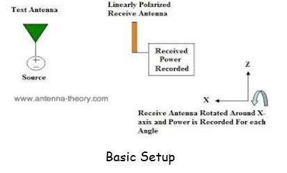
Polarisation Measurement
The polarization measurement method requires that a linearly polarized antenna, usually a dipole or a small horn, is rotated in the plane of polarization, which is taken to be normal to the direction of the incident field, and the output voltage of the probe is recorded. The recorded signal describes a polarization pattern for an elliptically polarized antenna. The polarization ellipse is tangent to the polarization pattern, and can be used to determine the axial ratio and the tilt angle of the AUT.
Considerations
Polarization is an important design consideration. The polarization of each antenna in a system should be properly aligned. Maximum signal strength between stations occurs when both stations are using identical polarization.
When choosing an antenna, it is an important consideration as to whether the polarization is linear or elliptical. If the polarization is linear, is it vertical or horizontal? If circular, is it RHC or LHC?
On line-of-sight (LOS) paths, it is most important that the polarization of the antennas at both ends of the path use the same polarization. In a linearly polarized system, a misalignment of polarization of 45 degrees will degrade the signal up to 3 dB and if misaligned 90 degrees the attenuation can be 20 dB or more. Likewise, in a circular polarized system, both antennas must have the same sense. If not, an additional loss of 20 dB or more will be incurred. Also note that linearly polarized antennas will work with circularly polarized antennas and vice versa. However, there will be up to a 3 dB loss in signal strength. In weak signal situations, this loss of signal may impair communications.
Cross polarization is another consideration. It happens when unwanted radiation is present from a polarization which is different from the polarization in which the antenna was intended to radiate. For example, a vertical antenna may radiate some horizontal polarization and vice versa. However, this is seldom a problem unless there is noise or strong signals nearby.
Applications
Vertical polarization is most often used when it is desired to radiate a radio signal in all directions such as widely distributed mobile units. Vertical polarization also works well in the suburbs or out in the country, especially where hills are present. As a result, nowadays most two-way Earth to Earth communications in the frequency range above 30 MHz use vertical polarization.
Horizontal polarization is used to broadcast television in the USA. Some say that horizontal polarization was originally chosen because there was an advantage to not have TV reception interfered with by vertically polarized stations such as mobile radio. Also, man made radio noise is predominantly vertically polarized and the use of horizontal polarization would provide some discrimination against interference from noise.
In the early days of FM radio in the 88-108 MHz spectrum, the radio stations broadcasted horizontal polarization. However, in the 1960’s, FM radios became popular in automobiles which used vertical polarized receiving whip antennas. As a result, the FCC modified Part 73 of the rules and regulations to allow FM stations to broadcast RHC or elliptical polarization to improve reception to vertical receiving antennas as long as the horizontal component was dominant.
Circular polarization is most often use on satellite communications. This is particularly desired since the polarization of a linear polarized radio wave may be rotated as the signal passes through any anomalies (such as Faraday rotation) in the ionosphere. Furthermore, due to the position of the Earth with respect to the satellite, geometric differences may vary especially if the satellite appears to move with respect to the fixed Earth bound station. Circular polarization will keep the signal constant regardless of these anomalies.
Conclusion
Polarization is a critical characteristic of an antenna.
Simply, if the receiver antenna is not polarized correctly with respect to the transmit antenna, it will not receive all the available power of the signal. This is independent of distance or other parameters. This can seriously degrade the performance of any communication system and unnecessarily waste a lot of power from the transmitter.
If there is a complete polarization mismatch, such as transmitting with a vertically polarized dipole antenna and receiving with a horizontally polarized dipole antenna, the received signal will be nearly zero no matter how much power is transmitted.
The author is a final year btech ece student at RSET ,Cochin