Efficient electronic design automation (EDA) calls for performing design layout, simulation and analysis using a single tool. The open source community delivers a software for the purpose in the form of eSim. Developed by a team from IIT Bombay, eSim packs a host of features and modules that make EDA comprehensive and simple. It is built using Python and merges KiCad circuit design software and Ngspice layout simulation package, which makes it a handy tool to develop and analyse new layouts and sub-circuits, or edit existing ones.
The latest version of eSim software has a gamut of modules that work in sync to provide a compact circuit layout framework and a simulation space-all under one roof. Let’s explore these different modules and how they make EDA easy.

Circuit design
Circuit design starts with schematic creation and netlist generation, followed by creating the component footprint and then finalising the circuit layout. KiCad tools like EEschema, CvPCB and PCBnew are meshed with eSim to enable circuit design.
Schematic creation with EEschema
EEschema is a popular tool for circuit schematic creation and editing. It allows you to draw the circuit and controls, which are passed down for creation of component footprints. EEschema manages the components library for eSim, enabling users to view, create or edit components. The netlist of the circuit is also developed here. It is the list of components and nodes that will be available in a circuit.
Component footprinting with CvPCB
CvPCB completes component layout on the PCB schematic. First, it helps in assigning the correct component footprints to the schematic and netlist generated by EEschema. Then it enables the user to place components on the schematic based on the footprints. Options like footprint filtering and list viewing, and 3D view of components help to avoid errors in the process. CvPCB has the capability to assign footprints automatically with equivalence tables, thus ensuring quick and accurate footprint association.
Layout formation with PCBnew
PCBnew works with EEschema and CvPCB to create PCB layout. Inputs are the schematic and netlist created by EEschema and PCB component layouts based on the footprint created by CvPCB. PCBnew has a plethora of features that help in creating an error-free PCB design. One such major feature is the design rules check (DRC), which points out any erroneous arrangement in the circuit in real time. The visual interface is a rat’s nest display, where components and nodes are connected by a hairline. Any movement made to the components moves the circuit along. Modifications made to the circuit schematic or components are automatically integrated by PCBnew. Effective auto-routers help in circuit production with export/import capability in SPECTRA dsn format. PCBnew also supports ultra-high-frequency circuit design.
Model framing
The eSim team has created two modules that can help users to create complex circuit models and hierarchies: Model Builder and Subcircuit Builder.
Model Builder
With the help of Model Builder, users can define the circuit model they want to build in eSim. Existing models can be edited as well. Circuit model options in Model Builder include diode, bipolar junction transistor (BJT), junction field-effect transistor (JFET), metal-oxide semiconductor field-effect transistor (MOSFET), magnetic core and IGBT.
Subcircuit Builder
Its main function is to create the sub-circuit for a component. The sub-circuit so created can be used in other circuits as well. Subcircuit Builder module has a feature to define new components like op-amps and IC 555. Users can also edit existing sub-circuits with this module.
Simulation
Built circuit layouts need to be verified for their validity, integrity and efficiency. Simulation software serves this purpose. eSim software includes a group of simulation tools to convert and visualise the circuit layout created using KiCad packages and Model Builder.
KiCad to Ngspice converter
The netlist generated by schematic editors needs to be converted into an Ngspice-compatible format. Developed in-house by the eSim team, the KiCad-to-Ngspice converter module helps to achieve that along with analysis parameters and source details. You can also add or edit device models and subcircuits present in the circuit schematic.
Simulation with Ngspice and NGHDL
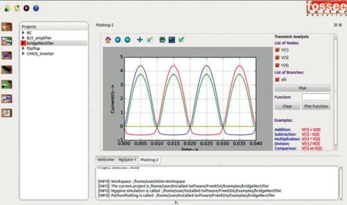
Ngspice is a popular circuit simulator tool integrated into eSim platform. It can analyse non-linear DC, non-linear transient and linear AC lines. It supports almost all essential components including inductors, resistors, capacitors, individual current and voltage sources, transmission lines (both lossless as well as lossy), switches and distributed resistor-capacitor lines. It also supports all types of models provided by Model Builder. After the schematic and model are selected and converted, Ngspice displays the analysis in a graphical user interface.
NGHDL is an add-on simulation suite that eSim uses for mixed-mode circuit simulation using simulation tool GHDL.
OpenModelica
This is a modeling and simulation tool with two modules: OMEdit, an integrated development environment (IDE) for the modeling and simulation logic, and OMOptim, another IDE for optimising the simulation. It incorporates Modelica programming language.
Working with eSim
The eSim platform is quite user-friendly, and supports Windows (7, 8, 10) and Ubuntu (12.04) operating systems. The main user interface (UI) is quite familiar, with menu bar, tool bar, dock area and console, project explorer and workspace. The toolbar allows users to access eSim modules as required.
Clicking ‘Schematic Editor’ button in the toolbar takes the platform to EEschema. EEschema has a series of toolbars that enlist the components and functionalities, which can be picked and placed on the workspace to create the circuit schematic. There are options of ‘Footprint Editor,’ which opens the CvPCB tool, and a layout editor, which opens the PCBnew tool. These steps create the netlist and the PCB layout.
The ‘Convert KiCad to NgSpice’ option enables format conversion. This section packs five tabs: Analysis, which sets the different parameters for analysing the circuit; Source Details, a dynamic tab scaled as per the number of power sources in the circuit; Device Modeling, which opens Model Builder; Subcircuits, which allows users to choose or create sub-circuits for components; and Ngspice Modeling, which opens the in-built Ngspice models. All this data needs to be entered. Once done, the conversion is processed. ‘Simulation’ button displays a Python plot of the circuit on a graphical user interface. The Ngspice-to-Modelica converter translates the simulated circuit in Modelica language, which is fed into the OMOptim for circuit optimisation.
The eSim library contains a comprehensive list of components and models. Users can also upload external library files to eSim.
Summing up
Developed under the Free and Open Source Software for Education (FOSSEE) initiative, eSim can be a decent alternative to commercial EDA solutions like OrCAD and HSPICE. The integration of PCB design and simulation in one package makes it a strong recommendation for basic- and medium-level users.