


Fizzim is a GUI-based, independent Finite State Machine (FSM) designing tool that offers flexibility of modifying the Verilog output without touching the GUI. Read this article to know how to start working with it.
Finite State Machines (FSMs) are frequently used in digital designs and FSM designing has become a common task for ASIC design engineers. FSMs can be coded directly into Verilog but one can always design them in a GUI and allow software to generate the Verilog code. Many GUI-based environments have been developed but no commercial tool has really been able to achieve widespread acceptance.

Fizzim is an open source graphical FSM design tool, the GUI for which is written in Java for portability and its back-end code generation written in Perl. Fizzim has its GUI and Verilog output independent of each other, with virtually everything being implemented as attributes, which allows for new backend (Verilog generation) features to be added without touching the GUI.
Starting Fizzim
 Java-based GUI makes Fizzim platform independent. It is distributed as a ‘.jar’ (Java archive) file and you can simply run it using Sun Java Runtime Environment.
You can open the executable jar file with the Java Runtime Environment or open terminal and run it using the following command line:
[stextbox id=”grey”]java –jar fizzim_v11.09.25.jar[/stextbox]
You can also add the fizzim file on the command line:
[stextbox id=”grey”]java–jar fizzim_v11.09.25.
jarfilename.fzm[/stextbox]
GUI
The easy-to-learn GUI offers intuitive options. You can create new states and transitions by right clicking in open space and selecting the option from the menu. Right clicking on an object gives you a menu to edit the object whilst double (left) clicking on an object will bring up the properties menu for that object. Select Edit -> undo or ctl+Z to undo and Edit -> redo or ctl+Y to redo. There is no limit on undo/redo.
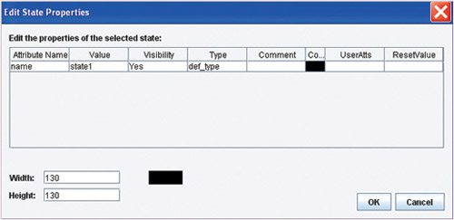
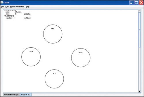
Creating new states. Let us take a simple FSM example, i.e., Cliff Cummings basic FSM to create a basic state machine using Fizzim. Right clicking and selecting New State opens a new menu as shown in Fig. 1. Change the state name as Idle and click OK. Repeat the same steps to create three more states as in Fig. 2. You can drag the states by left clicking and holding onto a particular state.
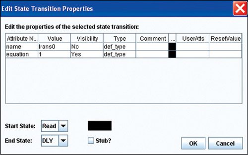
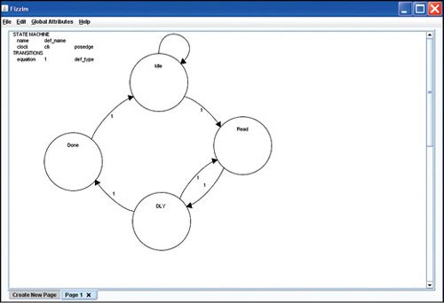
Creating transitions. To create a new transition, either right click on the start state and select Add State Transition to and the desired end state, or right click on the open space and select New State Transition, which opens a full menu as shown in Fig. 3. Select the start and end states in the menu. Perform these steps to have all the transitions as shown in Fig. 4.
Filling details. Everything in Fizzim is stored as attributes, either attributes on the FSM itself or attributes on individual states and transitions. So adding inputs, outputs, transition equations, etc is a matter of editing attributes. Also, state and transition object attributes have to be defined first in the global ‘states’ and ‘transitions’ attribute menus before they will be available in individual states and transitions.
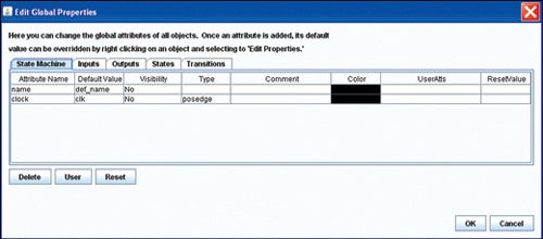
Select Global Attributes -> StateMachine from the top menu, which will open a menu as shown in Fig. 5. Change the module name cliff, the clock name clk and make it a posedge clk. Click the Reset button to get two more attributes to appear. One is reset_signal, change this to rst_n, negedge. Set reset_state to Idle via the pull-down menu and set its type to anyvalue (allzeros and allones will force the reset state to be all zeros or all ones, which we do not require in this example). Click OK, now Idle state has double rings to indicate that it is a reset state.
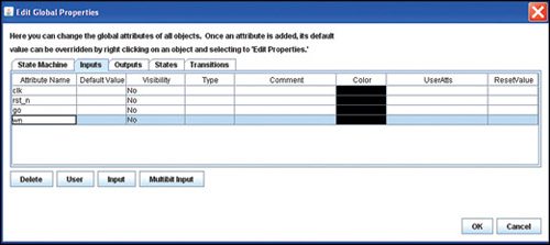
Select Global Attributes -> Inputs from the top menu that will open a menu and click on Input button to add inputs as shown in Fig. 6. Click OK to exit.

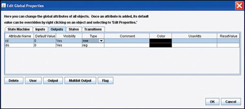
Select Global Attributes -> Outputs from the top menu, which will open a similar menu, or you can just switch to Outputs tab without exiting the menu. Click on Output button twice to add two outputs rg and ds. Select the Type field to reg and set Default Value to 0, and Visibility as Yes, as shown in Fig. 7.
You can switch over to States an Transitions tabs to see the values. Change the Visibility field in the Transitions tab to Only non-default, to make the 1 equation not show up on the diagram.
Note: rd and ds now appear as state attributes in States tab. This means you will be able to assign particular values to them in particular states. Transitions tab does not show rd and ds because it makes no sense to define registered outputs on a transition.
Individual state attributes. Now the outputs appear on the states with a <= after them as shown in Fig. 8. This indicates registered outputs (= means combinational).
To enter the non-default values for rd and ds, right click on the Read state and select Edit State Properties to bring up the menu, or just double click the Read state bubble. Change the value of rd to 1. Repeat this for the other states to add appropriate output values (rd = 1 in DLY, ds = 1 in Done).
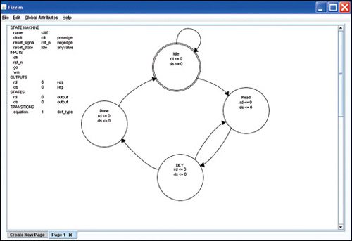
Individual transition attributes. Double click on the Idle to Read transition to bring up the transition menu. Change the equation to go. Repeat this for the state transition from DLY back to Read that has an equation of ws. Our final state diagram looks like Fig. 9, a Cliff Cummings’ basic FSM.
Output
Now we can run the backend and generate code using:
[stextbox id=”grey”]fizzim.pl < cliff.fzm > cliff.v[/stextbox]
(The default encoding is heros)
The default technique does not really allow for the default_state_is_x behaviour, so the output looks rather different when this attribute is set (refer to code generated). For implied_loopback as set assumption (setting either flag is not recommended as it can result in inferred latches), you can take output using onehot when implied_loopback is set by using:
[stextbox id=”grey”]fizzim.pl –enc onehot < cliff.fzm >
cliff.v[/stextbox]
Many designers prefer to design their FSMs as a state diagram (bubbles and arrows) and then manually translate this diagram into Verilog. For these designers, it would certainly be handy to design the FSM directly in a graphical tool and allow the software to generate the Verilog code.
We have discussed the basic operation of this tool whose simple and easy-to-use features, with a familiar Windows look and feel of GUI, clearly indicate that it is a handy tool for designing FSMs. The main feature which sets it apart is that its GUI is independent of Verilog generation, which allows for easy modification of the Verilog output that can be the main concern of many designers for better understanding and designing of FSMs.
Download latest version of the software: click here
