


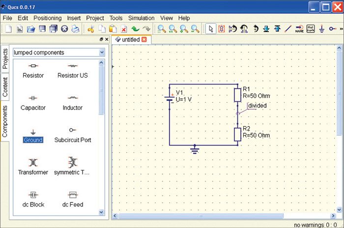
To edit the schematic, select the Components tab, it shows the lumped components (such as resistors and capacitors), sources (such as DC and AC sources), transmission lines (such as microstrip, coaxial cable and twisted pair), non-linear components (such as ideal op-amp, transistors), digital components (flip-flops), file components (Touchstone files, SPICE files), simulations (AC or DC analysis), diagrams (cartesian or polar plot) and paintings (texts, arrows and circles) (Fig. 4). Start working on the schematic by placing the components on the schematic area by draging and droping the desired components. You can also click a component once and then move the mouse cursor onto the schematic to click again and put it on that position. Also, you can right click during the mouse movement in order to rotate the components at their final positions.
Design and analysis
For better understanding of the tool, let us take an example of a simple voltage divider circuit and perform a DC steady-state analysis to compute node voltage and branch currents of the circuit.

Fig. 5 shows various components of the circuit placed in the schematic area using the above-mentioned procedure. These components can be connected using a wiring tool, and wiring mode can be enabled by clicking the wiring icon or by ctrl + E shortcut. Left click on the component’s ports (small red circles) to start a wire and click on the second port to finish the wire. If you want to change the orientation of the wire, right click on it or press ESC key to leave the wiring mode.
For any simulation, a reference potential is required (for the nodal analysis). The ground symbol can be found in the Components tab in the lumped components category, or you can select the same by using ctrl + G shortcut. Also, you need to place the ‘simulation’ block in the schematic for each simulation. For the current simulation, we will place DC Simulation block, which can be found in the Components tab in the Simulations category.
To get the voltage between the two resistors (the divided voltage) as an output in the dataset after simulation, you need to label the wire by double clicking the wire and giving an appropriate name, or by using ctrl + L shortcut. Also, you can choose Insert→Wire Label menu entry. Fig. 6 shows how the final circuit would look like after following the above steps.
Simulation
Select Simulation→Simulate menu entry to start the simulation. Alternatively, you can click the simulation button (gearwheel) or press F2 shortcut.
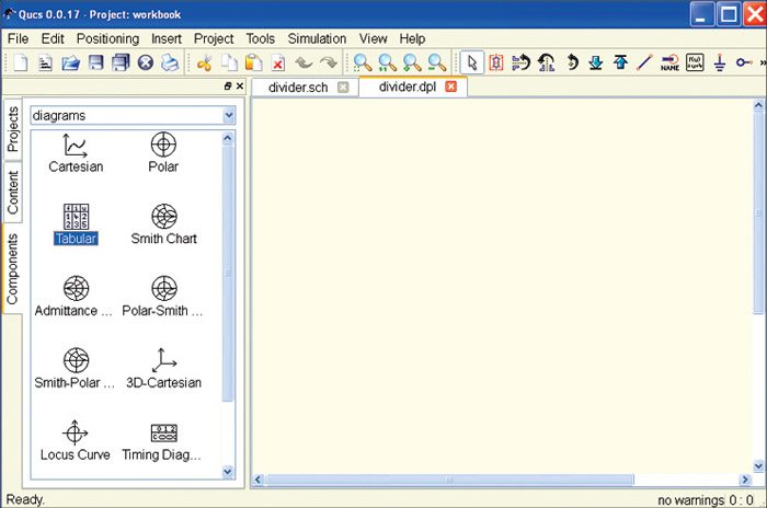
After the simulation, Components tab is changed to diagrams category and related data is displayed. Now you can choose the Tabular from diagrams and place it on the data display page. After dropping the Tabular, the diagram, a dialog box appears as shown in Fig. 7. Double click divided.V to add the graph (i.e., values in a Tabular plot) to the diagram. Similarly, other items listed in the dataset list can be put into the graph.
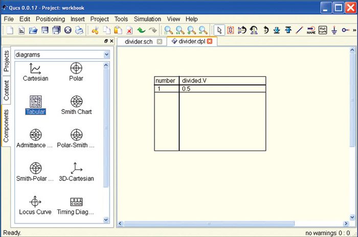
Now you can see the value of the node voltage divided.V, which is 0.5V. That was expected since the values of the resistors are the same and the DC voltage source produces 1V (Fig. 8).
Other features
Having made your first successful simulation of QUCS, now you can extend your simulation for a better understanding of the circuit by changing the component properties either by clicking on the divider.sch tab or using the F4 shortcut, or by selecting the Simulation→View Data Display/Schematic menu entry. Afterwards, double click on any resistor (say R1), which will open a component property dialog box where you can edit all the properties of the selected component. Change the values and properties of the component and observe the results.
Also, if you do not want QUCS to change automatically to the associated display data, you can change the behaviour of the document by changing the settings. You can go to the document settings dialog box by right clicking on the free space on the schematic area and selecting the Document Settings menu, item in the context menu which pops up or by selecting the File→Document Settings menu entry.
Useful tool
QUCS is an easy-to-use and handy tool for circuit designers. Not only it supports all kinds of simulation types but it also allows you to have multiple simulations with one design, by allowing you to change the parameters and properties of the components. QUCS helps in better understanding of the circuit design as well as components. Availability of mathematical equations makes it a useful tool for the designers and educators as well as learners.
The author is a technical journalist at EFY Gurgaon
