


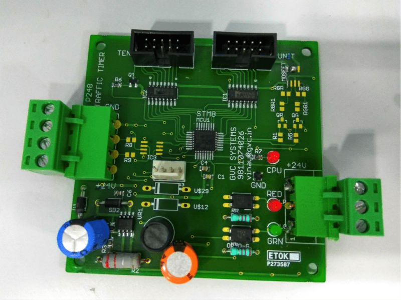
Almost all traffic signal carry a count down timer to indicate remaining time before red/green lights are turned off. This article explain the working, hardware and software for a traffic timer board as designed by the author for commercial use.
Here is a board that do same. This has board designed by GVC Systems Pvt. Ltd. and is sold to various installers across India.

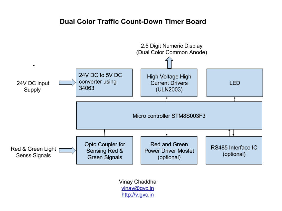
Traffic timer board block diagram
Board can be divided into following blocks for easy understanding. The brief description and circuit diagram is given on following pages.
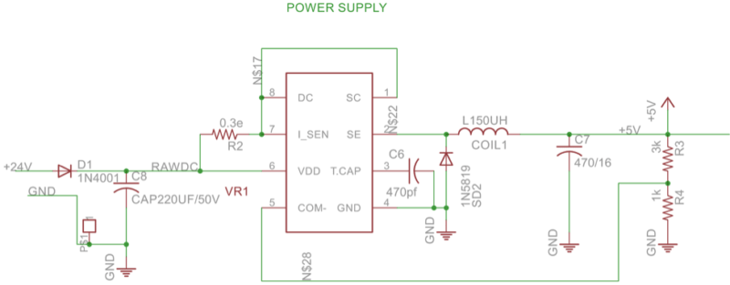
 24V DC to 5V DC

Traffic signals work on 24V DC and micro controllers / electronics
use 5V DC. So this part down converts 24V to 5V. We use a popular DC DC Converter MC34063. This is a high efficiency switched converter.
Microcontroller
We have used 8 bit controller STM8S003K3. Key specs are as below
● 8 bit with 8k flash and 1k ram
● 32 pin device with maximum 28 GPIO
● SPI, I2C, UART interfaces
● PWM, Timer, ADC
● Multipurpose Timer
● On board oscillator and reset circuit – no need to add extra crystal and reset circuit
We also have a 4 pin connector to program the micro controller using STVP software from and a low cost burner ST-LINK from STMircoelectronics.
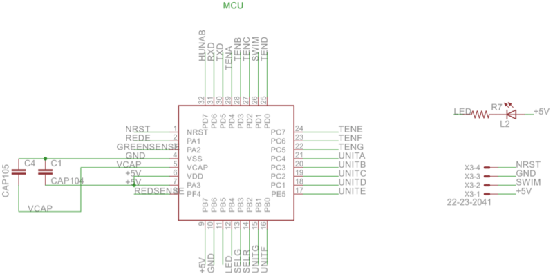
LED
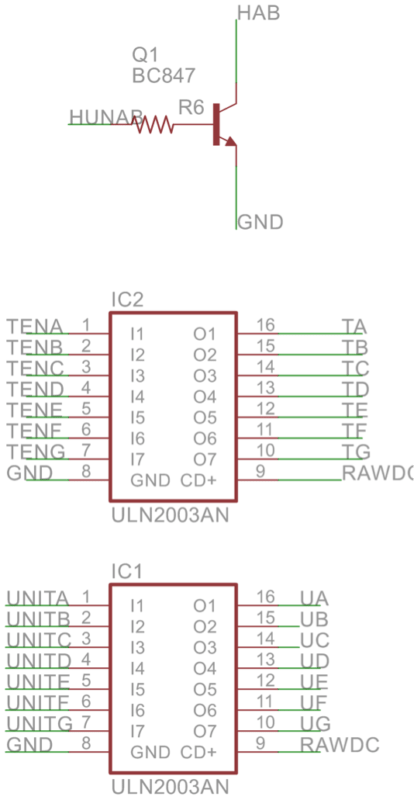
A single led is driven by a gpio pin of micro controller. This led blinks at 1 HZ rate to indicate that MCU is working.
High Voltage, High Current Driver
We need to drive large size seven segment numeric displays, Then need 24V DC and around 50 mAmps current per segment. Micro controller can not provide this. So we used ULN2003 to driver 14 segments (7 unt segments and 7 ten segments) and one pnp transistor to drive the single hundred’s digit.
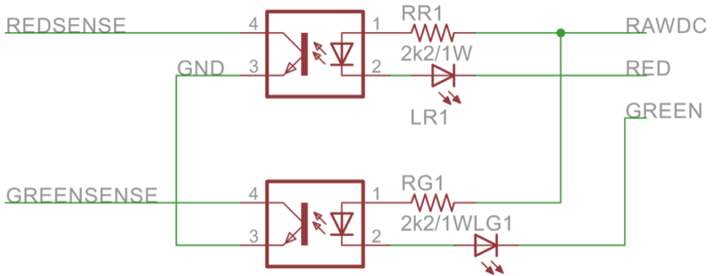
Optocoupler
Octocoupler to sense status of red/green light – we need to sense when light is on or off. As lights work on 24V and MCU can sense only 5V signals, So we use two opto couplers PC817 to convert 24V signals to 5V and sense the light status. When lights are on, the opto coupler diode is forward bias and output transistor is in saturation region. And micro get zero volt.When light is off, diode does not conduct and transistor remain off and MCU gets high signal. Software read and processes the signal.
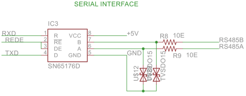
Optional RS485 interface
This is an optional circuit added in the board to communicate with traffic master card. In our present design we are not using this. This component may not be assembled in your sample.
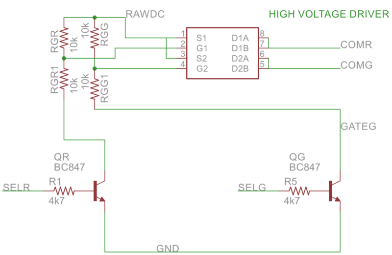
Optional Red and Green Anode Driver
This is also an optional circuit. This is used to display time of red signal in red color and time of green signal in green color. This is achieved by driving two independ common anode supply. The common anode supply for green display is switched on by software when green signal is on and common anode supply for red signal is switched on by software when red signal is on.
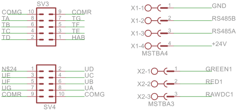
And here are all connectors in a single sheet
Software
The whole unit works with the software written in ‘C’ language using STVD from STMircoelectronics and cosmic c compiler from Cosmic Software
Software function
Here is a brief description of software. At power on our board is learning mode and display remain blank. It waits till any signal goes active and starts counting the time for which it remain on. The on time is stored in a variable and now board is in verify mode. Again when light is switched on, board starts counting the time for which light is on. The second on time is compared with first on time and if both are equal, then board enters normal operation mode and the time is saved as normal on time. Next time when light is switched on, the board knows the total time, it is going to remain on and so start displaying the remaining time.
Same thing happen for green light.
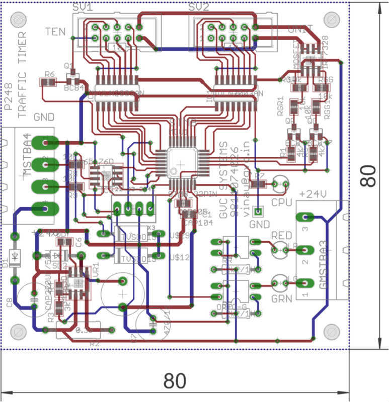
PCB Layout
PCB is of size 80 mm x 80 mm , double sided, PTH and gold plated. Here is PCB layout of the PCB for your reference
Suggested testing sequence
Testing software is an important part and you need to take care of all possible cases. Here is what we have done. Think and suggest if we missed some thing.
| Condition | Red Signal | Green Signal | Display |
| At Power On | Off | Off | Off |
| After power on | On | On | Er in Orange Color |
| Off | Off | Off | |
| Keep it on for 8 seconds | On | Off | L1 in red color |
| Off | Off | Off | |
| Keep it on for 8 seconds | On | Off | L2 in red color |
| Off | Off | Off | |
| Keep it on for 7/8/9 secs | On | Off | Countdown 8 to 1 |
Also, check the density-based Traffic Light Controller using Arduino.
Here are the eagle and Gerber Files:
