


This air-conditioner (AC) power saver circuit can control the operation of two separate AC units, reducing energy consumption during preset periods and cutting overall load and electricity bills.
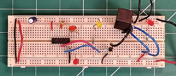
Compact and cost-effective, it is especially useful for large rooms or halls where two ACs are installed, enabling load balancing and energy savings without compromising comfort. Fig. 1 shows the author’s prototype on a breadboard.
POC Video Tutorial
Power Saver Air Conditioner Circuit and Working
Fig. 2 shows the circuit diagram of the AC power saver. It is built around IC CD4060 (IC1), a 2×6-way rotary switch (S1), two 12V SPDT relays (RL1 and RL2), two 1N4007 diodes, two 2N2219 NPN transistors (T1 and T2), and a few other components. The 2N2219 transistors are used to drive the 12V electromagnetic relays RL1 and RL2. These relays control the two AC units alternately based on timer intervals. The rotary switch (S1) is used to select the on and off times for each AC unit.

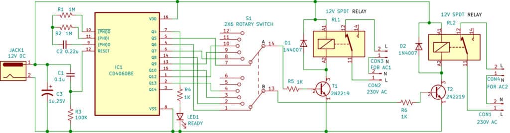
The heart of the circuit is the CD4060 IC, a 14-stage binary ripple counter with an inbuilt oscillator, which functions as a timer to generate automatic switching intervals. The blinking of LED1 indicates that the oscillator is functioning.
The timing is determined by external resistors R1 and R2 and capacitor C2, which are connected to pins 10, 11, and 9 of the IC. Based on these timing components, the output timings of the CD4060 are listed in the accompanying table. When power is applied, the CD4060 initiates its timing operation, and its outputs Q4 through Q13 alternate between high and low according to the values of the connected resistors and capacitor.
To select a 2×6 rotary switch (S1) for this application, it is important to understand its configuration. In this circuit, switch S1 is used to select different output pairs from the CD4060 timer IC. The switch has two common terminals: pin 14 (pole A) and pin 13 (pole B). As the knob is rotated through its six positions, each pole connects to one of the six corresponding terminals, allowing different output combinations to be selected. Only four positions of the rotary switch are used in this circuit (see Table 1).
