Alarm clocks are made to wake you up. However, it is quite bothersome to hear the alarm continuously until you get up and put it off. Also, you might fall asleep again. The snooze facility solves this problem to some extent by allowing you to turn the alarm off for a specific period of time by pressing a switch. But here again, you need to look for the snooze switch!
Here is a low-cost solution to these problems. This circuit wakes you up gently. It puts off the alarm after a predetermined time and makes it sound again after some time. And this process is automatic. You don’t need to press any switch, thanks to timer IC NE555, CMOS NAND gate CD4011, and a few discrete components.
Auto Snooze Circuit for Digital Alarm Clocks

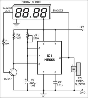
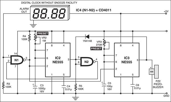
There are two types of auto-snooze circuits: one for a digital alarm clock with snooze facility (Fig. 1) and the other for a digital alarm clock without snooze facility (Fig. 2).
In the auto-snooze circuit for a digital alarm clock with snooze facility, the alarm output as well as the snooze facility of the clock are used. When the alarm’s output goes high at the predetermined time, transistor BC547 conducts to trigger pin 2 of IC1. As a result, output pin 3 of IC1 goes high and it makes the alarm sound as well as triggers the snooze. This results in sounding of the alarm for=1.1×VR1×C1 seconds and turning the alarm output off so that pin 2 gets triggered only for a moment. After the snooze time (9 minutes for clock chip MM5387) programmed in the clock IC is over, the alarm output goes high and triggers IC1 again, and this process continues until the alarm-off switch of the clock is pressed.

On the other hand, in the auto-snooze circuit for alarm clocks without snooze facility, first set presets VR2 and VR3, using the formula t=1.1RC, such that the time period of IC3 is less than the time period of IC2. For example, let the time constant of IC3 be 10 seconds and that of IC2 be 7 minutes. In such a setting the snooze time is 6 minutes 50 seconds and alarm-on time is 10 seconds.
In normal situation, the input of NAND gate N2 is low and thus its output at pin 4 is high. Consequently, the input at pin 2 of N1 is high. On the other hand, the input at pin 1 of N1 is kept low via resistor R3. At the predetermined time, when the alarm output from the clock goes high (also making pin 1 of N1 high), it makes output pin 3 of N1 low, which triggers both the monostables (IC2 and IC3) at pin 2. As a result, the input of gate N2 goes high and hence its output pin 4 as also pin 2 of gate N1 go low. Thus the output of N1 goes high immediately.
The output of IC3 switches on the alarm circuit and it sounds for 10 seconds. The output of IC2 remains high for 7 minutes. Diode 1N4148 prevents the alarm from staying ‘on’ after 10 seconds. After 7 minutes, the inputs of N2 go low and thus monostable IC2 gets triggered once again. This process continues as long as the alarm output of the clock is high.
The entire circuit can be powered from the 5V DC power supply of the clock. For louder sound you can use any alarm circuit with a suitable power supply in place of the piezobuzzer.
The article was first published in October 2003 and has recently been updated.


