

A reference design shows how to build an 80V source and measurement unit for chip testers that can supply, measure, and test semiconductor devices.
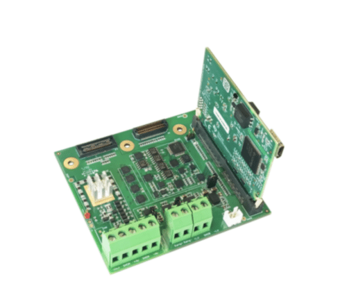
Automated test equipment (ATE) used in semiconductor manufacturing relies on source and measurement units (SMUs) to accurately apply voltages or currents to a device under test (DUT) while measuring its electrical response. As semiconductor devices become more complex and operate over wider voltage ranges, designers need SMUs that combine high accuracy, fast response, and electrical isolation. Texas Instruments‘ TIDA-010962 reference design demonstrates one approach to meeting these requirements through an 80V discrete floating voltage and current (VI) architecture.
The reference design is built to operate in four quadrants, allowing it to both source and sink voltage and current. It supports output voltages of ±40V or 0V to 80V, with current ranges of 500mA, 10mA, and 10µA. This flexibility enables the same hardware platform to characterize a wide range of semiconductor devices, from power components to low-current analog circuits.
A key feature of the design is its floating architecture. Instead of referencing the output directly to system ground, the measurement circuitry floats with respect to ground. This approach allows multiple channels to be connected in series or parallel when higher voltages or currents are required, while reducing ground-loop issues that can affect measurement accuracy. The design also supports ganging and stacking of channels, making it suitable for modular ATE systems.
Precision signal generation begins with a 20-bit digital-to-analog converter (DAC), which produces the reference voltage for the force circuitry. High-resolution measurements are captured using an 18-bit dual-channel analog-to-digital converter (ADC). Together, these converters enable fine control of output levels and accurate measurement of the DUT response across different operating ranges.

The force circuitry can operate in force-voltage (FV) or force-current (FI) mode. In force-voltage mode, the system regulates the output voltage while monitoring the resulting current. In force-current mode, the output current is controlled and the resulting voltage is measured. A buffer mode is also available to isolate the output from external circuitry while maintaining signal integrity. These operating modes allow engineers to perform a variety of electrical characterization and production test functions using the same hardware.
To achieve accurate current measurements over several decades of current, the design uses multiple current ranges. Range switching allows the system to maintain high measurement resolution whether testing low-leakage devices in the microampere range or higher-power devices that require hundreds of milliamperes. According to the design guide, the reference design achieves approximately 0.01% accuracy after calibration, making it suitable for precision semiconductor testing.
Dynamic performance is equally important in production environments where test throughput affects manufacturing cost. The reference design provides a rise time of approximately 50µs and a settling time of about 20µs, enabling rapid transitions between test conditions. It is also designed to remain stable while driving capacitive loads greater than 100µF, an important consideration when testing devices or circuits with significant input capacitance.
TI has tested this reference design. It comes with a bill of materials (BOM), schematics, assembly drawing, printed circuit board (PCB) layout, and more. The company’s website has additional data about the reference design. To read more about this reference design, click here.