


 Presented here is a simple filtering and polarity reverse protection guard for AC/DC power adaptors. Wall adaptors have many advantages because these are low-cost, have a wide range of output voltages and currents, are easily available, come with input and output cables of different fixed lengths and so on. But these have some disadvantages, too, such as high ripples, output noise, RFI/EMC and unwanted transient responses. Again, output polarity of adaptors may vary for the same type of connectors.
Some of these drawbacks can be reduced with additional circuitry, as proposed here, which reduces the ripples by about ten times and limits undesirable radio emissions from cables of the adaptors.
Circuit and working
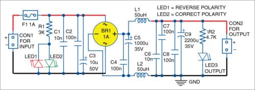
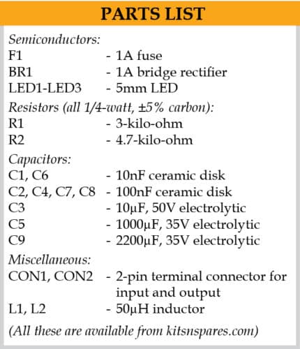
The circuit diagram of the filter and polarity guard for the wall AC/DC adaptor is shown in the figure. It is built around a bridge rectifier (BR1), two inductors (L1 and L2), three LEDs, and a few capacitors and resistors.
The circuit has input polarity indicators LED1 and LED2, input fuse F1, input high frequency filter, bridge rectifier BR1, output LC filter and output voltage indicator LED3. Input polarity indicators show the polarities of input AC or DC power connections at connector CON1.
LED1 indicates reverse polarity, whereas LED2 indicates correct polarity of the input signal. Irrespective of input connections, polarities of output voltage at CON2 will not change. LED3 is on when output voltage is present at CON2.
Input filter is built around capacitors C1, C2 and C3 to stop the high frequency noise at input of the device. BR1 is used to ensure that output voltage does not depend on input polarity and, consequently, has fixed polarity. At output of BR1, there is a set of capacitors for reducing ripples and noise coming from the wall adaptor. After that, L1 and L2 further reduce the ripples and noise.
Output capacitor C9 provides good filtration at low frequencies and high output peak current. You can calculate the current capacity of this capacitor with the following relationship:
I=C×(dV/dT)
Here, I is the instantaneous current through the capacitor in amperes. C is capacitance in Farads. dV is change in voltage of capacitor in volts. dT is time interval or duration of the pulse applied on the capacitor in seconds. dV/dT is the instantaneous rate of voltage change over the capacitor as volts/second.
L1 and L2 are selected according to required output current and suppression of noise and ripples. All capacitors should be rated for at least 35V because most are designed for 19V and above.
Construction and testing
It is easy to assemble the circuit on a Veroboard. The circuit does not require any adjustments to work properly. Input fuse F1 is selected according to the wall adaptor output rating.
Using the circuit is simple. Connect output of the adaptor to CON1. Then, connect output voltage from CON2 to the load or target device.
The circuit is simple but useful for wall AC/DC adaptors where it is important to reduce ripples and noise, and improve transient response of the adaptors. It can also be used in a wide range of switching and analogue power supplies.
The circuit has been developed for 26V and 19V wall adaptors, but by replacing some components, it can be used for other wall adaptors with output voltage starting from 5V. When input polarity is fixed, the bridge can be replaced with simple diodes depending on requirement.
Petre Tzv Petrov was a researcher and assistant professor in Technical University of Sofia (Bulgaria) and expert-lecturer in OFPPT (Casablanca), Kingdom of Morocco. Now he is working as electronics engineer in the private sector in Bulgaria