


This delay-off timer is a cost-effective, reliable, and easy-to-assemble device for automating time-based switching operations. It improves energy efficiency and adds convenience in both home and office settings by ensuring appliances remain on only as long as required.
Delay-off timers are commonly used in appliances that need to remain active for a defined duration even after the control switch or trigger has been turned off. They contribute to convenience, safety, and power savings across residential, commercial, and automotive applications.
POC Video Tutorial:
Typical uses include exhaust fans in bathrooms and kitchens, where the timer keeps the fan running briefly to eliminate residual moisture or odours. In staircases or corridors, it ensures lights remain on just long enough for safe passage. Other applications include automatic water pumps, car interior lighting, and buzzers or alarms.

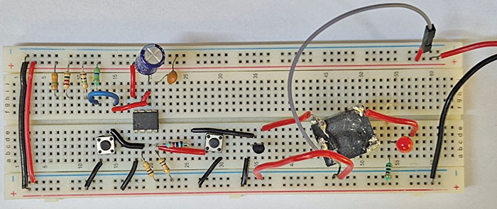
This timer circuit is built around a TLC555 IC configured in monostable mode. Once the start switch is pressed, the circuit powers the connected appliance for a preset interval before automatically switching it off. Dedicated push switches allow selection of delay options—5, 10, 15, 20, or 30 minutes—based on the switch used. Fig. 1 shows the timer circuit on a breadboard.
| Parts List |
| Semiconductors: IC1 – LM7812, 12V regulator IC2 – TLC555 timer T1 – 2N2219 NPN transistor D1 – 1N4007 rectifier diode D2 – 1N4148 signal diode BR1 – 1A bridge rectifier LED1 – 5mm LED Resistors (all 1/4-watt, ±5% carbon): R1-R3 – 1kΩ R4 – 580kΩ R5 – 1.2MΩ R6 – 1.8MΩ R7 – 2.2MΩ R8 – 3.3MΩ R9 – 680Ω Capacitors: C1 – 1000µF, 35V electrolytic C2 – 470µF, 35V electrolytic C3 – 10nF, ceramic disc Miscellaneous: CON1-CON3 – 2-pin connector RL1 – 12V SPDT relay S1, S2 – Push-to-on switch S3-S7 – On/off switch X1 – 230V AC primary to 12V AV, 500mA secondary transformer – Wires and jumper wires, as needed – 230V AC appliance – 230V AC power cord |
Delay-Off Timer Circuit and Working
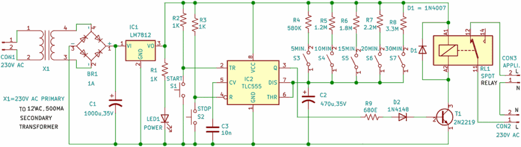
Fig. 2 shows the circuit diagram of the delay-off appliance timer. It is powered by 230V AC mains supply, which is stepped down to 12V, 500mA by a transformer, rectified using a bridge rectifier (BR1), filtered by capacitor C1 (1000µF, 35V), and regulated to 12V using an LM7812 (IC1). This regulated 12V supply powers the remaining circuit.
A power LED (LED1) indicates the supply status. If LED1 is lit, the power is on; if LED1 is unlit, the power is off.
The TLC555 timer (IC2), the heart of the circuit, is configured in monostable mode. The timing capacitor C2 (470µF, 35V) and one of the resistors R4 through R8 (selectable via switches S3 through S7) determines the off-delay time. Momentarily pressing the start switch (S1) triggers IC2, causing its output to go high for the preset duration. During this time, the NPN transistor 2N2219 (T1) conducts and energises the relay (RL1). The connected appliance across CON3 receives power through the relay contacts, provided that CON2 is connected to a 230V AC source.
Once the set time elapses, the output of IC2 goes low, cutting off transistor T1 and de-energising the relay, thereby switching off the appliance. The stop switch (S2) can be used to stop the appliance at any time during the countdown immediately.
The circuit is designed with five preset time-delay options, selectable via push-button switches. Switch S3 sets a 5-minute delay, switch S4 for 10 minutes, switch S5 for 15 minutes, switch S6 for 20 minutes, and switch S7 for 30 minutes. These switches determine the resistance in the RC timing network, thereby setting the desired delay duration.
In addition to the core components, several supporting elements ensure reliable operation. Diode D1, connected across the relay coil, acts as a flyback diode to clamp high-voltage spikes and protect transistor T1 and nearby components. Diode D2 blocks reverse voltage to protect the base-emitter junction of T1, limits the base current for safe operation, and enhances switching reliability. Resistor R1 serves as a current-limiting resistor for LED1, while capacitor C3 (10nF) functions as a noise filter on the control pin of the TLC555 timer, thereby improving stability and preventing false triggering.
Construction and Testing
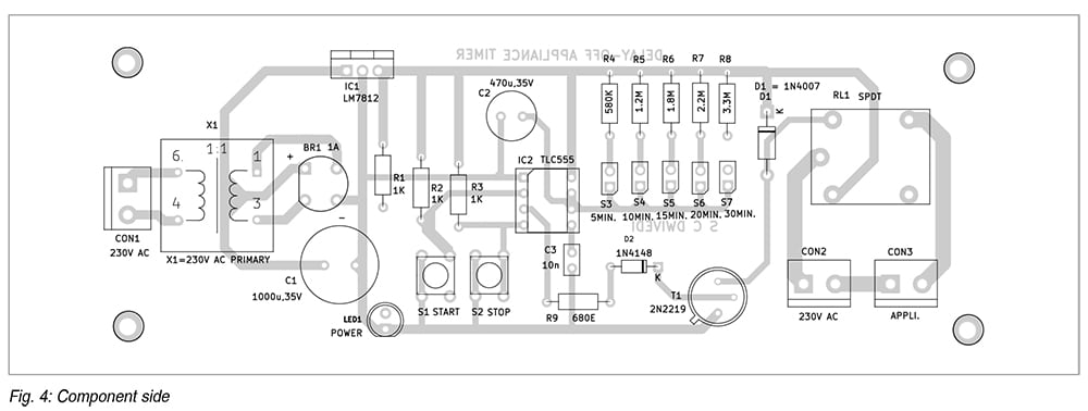
An actual-size, single-sided PCB layout for the delay-off appliance timer is shown in Fig. 3, with the component layout in Fig. 4. After assembling the components on the PCB, the circuit should be enclosed in a suitable cabinet, ensuring proper openings are provided at the rear for mounting and ventilation. The switches (S1 through S7) should be mounted on the front panel of the cabinet and connected to the PCB using external wires.
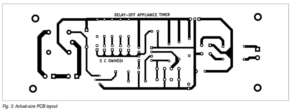
Alternatively, the components can be assembled on a general-purpose PCB if a custom-designed PCB is not available. It is vital to ensure proper heat dissipation for the LM7812 voltage regulator. A small heat-sink should be attached to the regulator to prevent overheating.
Before powering the circuit for the first time, all connections should be carefully verified and double-checked to ensure accuracy. The polarities of the electrolytic capacitors, diodes (D1 and D2), and the transistor (T1) must be checked. Ensuring correct orientation and secure connections is essential to prevent component damage and to ensure reliable operation.
To test the circuit, a 230V AC appliance, such as a lamp or fan, should be connected. The desired delay time can be selected by pressing one of the selector switches (S3 through S7). Then, the start switch (S1) should be pressed to trigger the monostable timer circuit. This energises the relay and powers the connected appliance. The appliance will remain on for the selected delay duration. Once the preset time has elapsed, the TLC555 timer output goes low, de-energising the relay and automatically turning off the appliance.
If required, the stop switch (S2) can be pressed at any time to manually interrupt the operation and turn off the appliance before the timer completes
its cycle.
Bonus: Watch the complete step-by-step video tutorial for this Delay-Off Timer Circuit.
S.C. Dwivedi is an electronics enthusiast and circuit designer at EFY