


 The purpose of this circuit is to create a new topology with good power factor maintained at AC voltage input, to provide good efficiency output to the battery and to increase its life.
Circuit diagram of the dual-voltage rechargeable torch light is shown in Fig. 1. It is built around two mylar 0.82µF capacitors (C1 and C2), four rectifier diodes 1N4007 (D1 through D4), two 3.7V, 860mAh lithium-ion rechargeable batteries (BATT.1 and BATT.2), two 5mm LEDs (LED1 and LED2), two one-watt LEDs (LED3 and LED4) and a few other components.
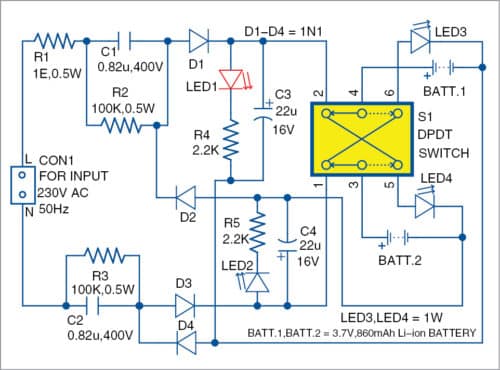
Charging of the two batteries is done via the circuit using capacitors C1 and C2 and resistors R2 and R3. Two sets of RC parallel circuits are used to step down 230V AC mains voltage before giving it to the batteries. Diodes D1 and D2 are used for rectification purposes. It is recommended to use 4.7V Zener diode across capacitors C3 and C4.
Positive half cycle of the AC mains charges BATT.1, and negative half cycle charges BATT.2. Capacitors C3 and C4 are filtering elements used to reject ripples and harmonics present in DC voltages.

Both LED3 and LED4 are one-watt white LEDs used for the torch application.
For charging the two batteries, keep DPDT switch S1 towards positions 1 and 2, and connect 230V AC input across CON1. The batteries’ charging status is indicated by the glowing of LED1 and LED2. After charging the batteries, the circuit can be used for the torch light. For using as a torch, keep S1 towards positions 5 and 6, so the white LEDs (LED3 and LED4) will glow.
Construction and Testing
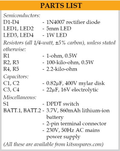
A PCB layout of the dual-voltage rechargeable torch light is shown in Fig. 2 and its components layout in Fig. 3. Assemble the circuit on the PCB. Connect 230V AC into the PCB across CON1. Connect LED3 and LED4 for the torch and two lithium-ion batteries for charging.
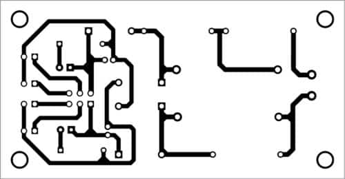
Download PCB and component layout PDFs: click here
- Manual Cut-Off: Because this circuit lacks an automatic cut-off, turn off the power source after charging to prevent battery damage.
- Caution for High Voltage: To avoid electrical dangers, always turn off the 230V AC mains before handling the circuit.
- Extended Battery Life: Proper circuit design reduces charge/discharge cycles, increasing battery life.
Caution
Care should be taken to avoid electric shock while handling 230V AC mains power supply. Also, it is essential to ensure that AC mains supply is switched off after charging because the circuit does not have automatic cut-off feature when the batteries are fully charged.
V. Vinoth is assistant professor in Imayam College of Engineering, Tamil Nadu and an electronics hobbyist
This article was published on 16 March 2020, and recently updated 30 October 2024.