


Introduction Many communications systems are powered via a 48 V backplane. This voltage is normally stepped down to a lower intermediate bus voltage, typically to either 12V, 5V, or even lower, in order to power the racks of boards within the system. However, most of the subcircuits or ICs on these boards are required to operate at voltages ranging from 3.x V down to as low as 0.5 V at currents ranging from tens of milliamps to hundreds of amps. As a result, point-of-load (PoL) dc-to-dc converters are necessary to step down from these higher bus voltages to the lower voltage necessitated by the subcircuits or ICs. As if this is not difficult enough by itself, these rails also have strict requirements for sequencing, voltage accuracy, margining, and supervision that also need to be considered!
Since there can be hundreds of PoL voltage rails in communications equipment, system architects need a straightforward way to manage these rails with regards to their output voltage, sequencing, and maximum allowable current. Many of today’s deep submicron IC digital processors demand that their I/O voltage rise before their core voltage. Alternatively, many DSPs require their core voltage to be brought up before their I/O. Moreover, power-down sequencing is also necessary. Accordingly, system architects need an effortless way to make changes to optimize system performance and to store a specific configuration for each dc-to-dc converter in order to simplify the design effort.
Moreover, most communications equipment manufacturers are being pushed to increase the data throughput rate and performance of their systems, as well as adding more functionality and features. At the same time, pressure is being applied to decrease the system’s overall power consumption. For example, a typical challenge is to reduce overall power consumption by rescheduling the work flow and moving jobs to underutilized servers, thereby enabling shutdown of other servers. To meet these demands, it is essential to know the power consumption of the end-user equipment. Thus, a properly designed digital power management system (DPSM) can provide the user with power consumption data, which in turn allows for smart energy management decisions to be made.

A principal benefit of DPSM is reduced design cost and faster time to market. Complex multirail systems can be efficiently developed using a comprehensive development environment with an intuitive graphical user interface (GUI). Such systems also simplify in-circuit testing (ICT) and board debug by enabling changes via the GUI instead of soldering in white wire fixes. Another benefit is the potential to predict power system failures and enable preventive measures, thanks to the availability of real-time telemetry data. Perhaps most significantly, dc-to-dc converters with digital management functionality allow designers to develop green power systems that meet target performance (compute speed, data rate, etc.) with minimum energy usage at the point of load, board, rack, and even at the installation levels, which reduces infrastructure costs and the total cost of ownership over the life of the product. After all, the largest operating cost of a data center is the cost of the electricity used to power the cooling systems to keep the inside of the data center below its predefined optimum operating temperature.
In addition, systems architects still need to have some relatively simple power converters to satisfy the various other power rails on their boards but have an ever-shrinking board area on which to place them. This is due, in part, to not being able to fit these converters on the underside of their circuit boards due to a 2 mm maximum component height restriction forced on them due to the multiple boards placed side-by-side in a rack mounted configuration. What they would really like to have is a complete power supply in a small form factor that does not exceed 2 mm when mounted onto a printed circuit board (PCB). Fortunately, such solutions do exist and will be discussed in more detail herein.

Converter Solutions
Analog Devices Power by Linear µModule regulators are complete system-in-package (SiP) solutions that minimize design time and solve the common problems of board space and power density issues routinely found in communications systems. These µModule products are complete power management solutions with integrated dc-to-dc controller, power transistors, input and output capacitors, compensation components, and inductors within compact, surface-mount BGA or LGA packages. Designing with Power by Linear µModule products can reduce the amount of time needed to complete the design process by as much as 50%, depending on the complexity of the design. This family of µModule regulators transfers the design burden of component selection, optimization, and layout from the designer to device, thereby shortening overall design time and system troubleshooting, as well as ultimately improving time to market.
These µModule solutions integrate key components commonly used in discrete power, signal chain, and isolated designs within a compact, IClike form factor. Supported by Power by Linear’s rigorous testing and high reliability processes, our µModule product portfolio simplifies the design and layout of power management and conversion designs. The product family embraces a wide range of applications including point-of-load regulators, battery chargers, DPSM products (PMBus digitally managed power supplies), isolated converters, battery chargers, and LED drivers. As highly integrated solutions with PCB Gerber files available for every device, these µModule power regulators address time and space constraints while delivering high efficiency and reliability. Furthermore, many of our newer products enable low EMI solutions that are compliant to EN 55022 Class B standards. This gives the system designer the confidence that the end system will meet the strict noise performance criteria needed to comply with the many noise immunity industry standards the end system must meet.
Moreover, as design resources become stretched by increased system complexity and shortened design cycles, the focus falls on development of the key intellectual property of the system. This often means the power supply gets put to one side until late in the development cycle. With little time, and perhaps limited specialist power design resource, there is tremendous pressure to come up with a high efficiency solution with the smallest possible footprint, while utilizing the underside of the PCB as well for maximum space utilization.
This is a key area where a µModule regulator can provide an ideal solution. The concept is complex on the inside, yet simple on the outside—the efficiency of a switching regulator and the design simplicity of a linear regulator. Careful design, PCB layout, and component selection are very important in the design of a switching regulator and many experienced designers have smelt the distinctive aroma of a burning circuit board in the early days of their career. When time is short or the power supply design expertise is limited, the readymade µModule regulator not only saves time and space but also reduces risk to the program.
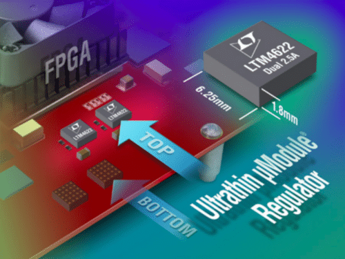
A recent example of an ultrathin µModule solution is the LTM4622. This is a dual 2.5 A or single two-phase 5 A output step-down power regulator in a 6.25 mm × 6.25 mm × 1.8 mm ultrathin LGA package. At nearly the height of a soldered down 1206 case size capacitor, its ultrathin height allows mounting on the topside of the board. The thin profile allows it to meet demanding height restrictions such as those required by PCIe and advanced mezzanine cards in embedded computing systems, as shown in Figure 1.
Furthermore, the LTM4622A was recently released. A variant of the LTM4622, this A version has a higher output voltage of 1.5 V to 12 V, in lieu of the non-A version at 0.6 V to 5.5 V. This enables the system designer to have a broader output voltage range on the higher end if the end system needs it. In either case, the input voltage range is 3.6 V to 20 V. Power by Linear’s µModule dc-to-dc regulators also provide a straightforward way to deliver both high power and DPSM capability. Since many of the µModule regulators can be paralleled for high load current with precision current matching (within a nominal 1% of each other), they can mitigate the potential for hot spots. Moreover, only one of the µModule regulators needs to contain DPSM capability, since it can supply the complete digital interface even if the rest of the µModule devices in parallel do not have DPSM capability built-in.
With DPSM devices, a system designer can do many different things, including the following:
- Configure voltages, define complex on/off sequencing arrangements, define fault conditions such as OV and UV limits, and set important power supply parameters such as switching frequency, current limit, etc. over a digital communications bus.
- Over the same communication bus, one can readback important operating parameters such as input voltage and output voltage, input and output current, input and output power, and internal and external temperature, as well as, in some of our products, measure energy consumed.
- Individuals can implement very precise closed-loop margin testing of their designs, as well as trim power supply voltages to very precise levels.
- These devices have been designed to be autonomous. Once they are configured and input power is applied, they sequence up the power supplies, regulate very accurate voltages at the point of load, continuously supervise voltage and current while implementing the user configurable fault management scheme, and arm a nonvolatile fault recorder that stores information about the power system at the time of a detected fault.
- DPSM devices can be cascaded to build large power supply systems that are coherent. This is achieved with an interchip coordination bus that operates at wireline speeds.
- They include internal NVM for device configuration and fault logging capability.
- These devices contain I 2 C/PMBus communication ports and use an industry-standard PMBus command set to control and manage the power system.
- These PSM devices are all supported by a common LTpowerPlay GUI. LTpowerPlay is an engineering-level GUI that was developed with power system design and debug in mind, as well as remote customer support.
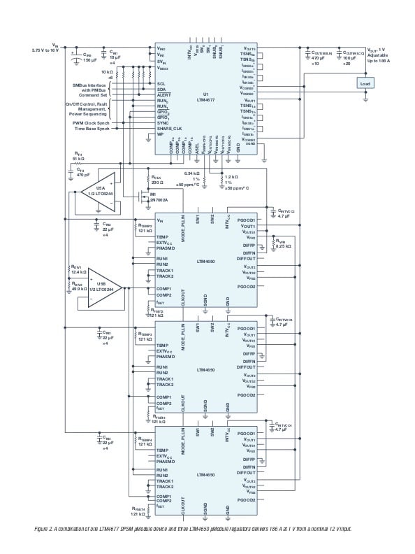
Accordingly, Figure 2 shows an application schematic of one LTM4677 (36 A DPSM µModule regulator) in parallel with three LTM4650s (50 A µModule regulators) for an 180 A plus DPSM PoL solution.
Conclusion
Having DPSM capability and ultrathin profile power conversion devices in today’s communications equipment provides the power supply designer with simple and powerful ways to deliver high power outputs to core voltages as low as 0.5 V with ±0.5% maximum dc output error over temperature, such as those needed by the newest sub-20 nm ASICs, GPUs, and FPGAs. Should there be a profile constraint, the utilization of an ultrathin profile μModule regulator, such as the LTM4622A, with a profile of less than 2 mm when mounted on the board, allows the use of board space on the underside which would otherwise be left underutilized. This not only saves expensive PCB real estate, but reduces the amount of required cooling due to its overall operating efficiency.
Finally, using µModule regulators makes sense in communications equipment since they can significantly reduce the debug time and allow for greater board area usage. This reduces infrastructure costs, as well as the total cost of ownership over the lifetime of the system. It’s a win-win for the companies that design and build this equipment and for the companies that use them once they have been installed in their data centers.

Thank you for the auspicious writeup. It in fact was
once a enjoyment account it. Glance advanced to more introduced agreeable from you!
However, how can we keep up a correspondence?