


For wireless access points or customer premises equipment (CPE), it can be hard to fully account for thermal management and the parameters affected by it prior to FCC certification. To save yourself the headaches of last-minute changes due to interference, coexistence or RF front-end (RFFE) linearity, be sure to design using component thermal parameters in mind. This blog post explains the biggest thermal challenges facing Wi-Fi front-end designs.
Increasing capacity for smart homes
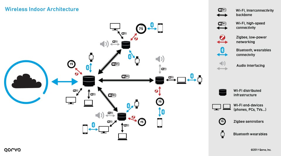
 On average, today’s households have 12 clients or Internet of Things (IoT) products communicating with each other, but these numbers will increase in coming years. Intel believes the number of household clients will increase to 50 in 2020, while Gartner predicts 20.4 billion connected things will be used worldwide by 2020.
In today’s wireless homes, communication operators and retailers have typically offered one large wireless router, using raw power to achieve coverage across the entire home. But with the sharp increase of household devices and the IoT, smart homes are pushing the capabilities of the single-router model.

As a result, new application models are evolving. Consumers are finding that placing more routers, or nodes, in the home helps service more clients and data backhaul to the home router/modem. This new mesh network model ensures wireless capability across a home using some techniques that are already present in office headquarters, hospitals and college campuses via enterprise-level systems.
The IoT challenge
It’s no surprise that the RF complexity within the access point increases because of this mesh networking model and as devices integrate more standards and capabilities.
The IoT brings several challenges:
- The addition of wireless radio needs. Access points today incorporate more than just Wi-Fi — they also support Zigbee, Bluetooth, Bluetooth Low Energy (BLE), Thread and narrowband IoT (NB-IoT). Operators are also finding ways to reach households who previously didn’t have access. Operator-supported LTE-M (the machine-to-machine version of LTE) is one example finding its way into some Wi-Fi gateways.
- More users within each home. Homes no longer have only one or two PCs and a few phones. Today, several computers, TVs, smartphones, wearables, security networks, wireless appliances and more all connect to Wi-Fi and the internet.
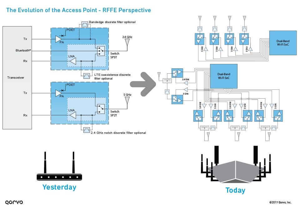
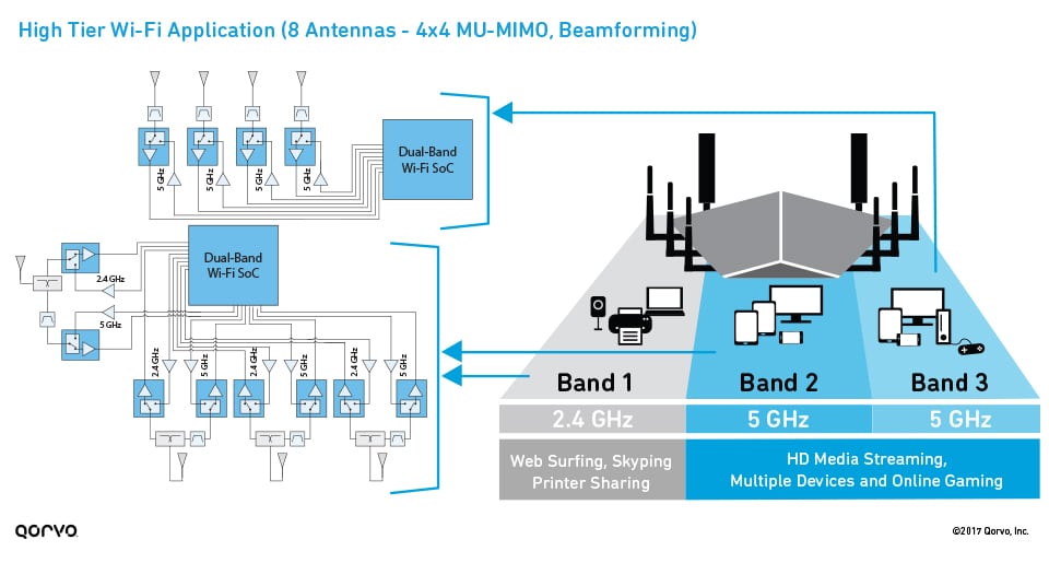
- Additional Wi-Fi bands. Units no longer have one 2.4 GHz band and one 5 GHz band. Now there are up to eight individual 2.4 GHz and eight 5 GHz paths. This change gives us the MIMO (multiple input / multiple output) and multiuser MIMO (MU-MIMO) paths within the Wi-Fi access point or node.
- Shrinking size and expanded functionality. Wi-Fi manufacturers are making Wi-Fi units smaller, sleeker, more decorative and less obtrusive. They’re also making some units all-weather or adding multifunctionality such as night-light capability.
Block diagrams of older vs. new access points highlight just how complex the RFFE design is now.
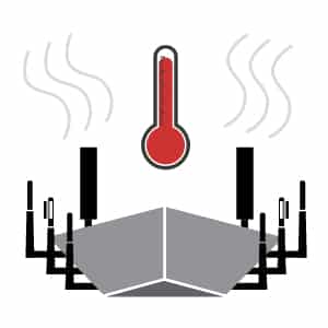
Running hot
All these changes in the Wi-Fi front-end design increase the number of RF chains, contributing to the overall heat within the access point. This increase in unit temperature also increases the RF tuning challenges, especially when the size of the box is the same or even smaller.
In the Wi-Fi world, one of the most critical design challenges engineers need to address is product temperature. In today’s products, components are subject to average temperatures of 60°C or greater, while sitting in a room temperature environment of 25°C. It’s important to consider this fact early on in a design, to help minimize redesign issues or additional costs.
How heat challenges RF front ends to deliver capacity and range
Temperature affects three RFFE components:
- Power amplifiers
- RF switches and low noise amplifiers (LNAs)
- Filters
Let’s examine the heat challenges and Wi-Fi design considerations for each category.
#1: How does the power amplifier factor in?
Engineers often balance between linearity, power output and efficiency in each of the RF chains. Using optimized, highly linear power amplifiers or front-end modules (FEMs) optimizes system efficiencies, creating less overall heat. It also reduces processing inefficiencies.
RF engineers should also consider several Wi-Fi design trends that affect power amplifiers:
-
- Use of time division duplexing (TDD). Wi-Fi networks use TDD, which means the PAs are pulsed on and off during operation — alternating transmit and receive functions. This increases PA transients, which attribute to high temperatures.
- More difficult error vector magnitude (EVM) specifications. EVM is a measure of modulation quality and error performance. In 802.11ac, the EVM specification was -35 dB, but in the next standard of Wi-Fi, 802.11ax, this specification increases to -47 dB — which is more difficult for Wi-Fi component designers to meet. Design engineers must design highly linear FEMs to optimize for EVM, which ultimately helps reduce overall product temperature.
- Higher modulation schemes. To help achieve higher capacity and data rates, Wi-Fi designs are moving from 256 QAM to 1024 QAM modulation schemes. With 1024 QAM modulation, there are more bits per symbol — 10 bits per symbol versus 8 bits in 256 QAM. However, as the data rate increases, EVM on the RFFE becomes a principal concern. The constellation is so dense in 1024 QAM that the processor must use sophisticated system decoding to distinguish each point. When the processor works harder, the unit device heat increases.
- How the RFFE performance affects the overall current draw on the system processor. Poor RF front-end performance means the processor will have to work harder to meet overall system requirements. Working the processor more increases system hardware heat.
#2: What about the RF switch and low noise amplifier (LNA)?
In the switch, insertion loss can also generate excess heat. When insertion loss increases and signal strength is lowered, the PA works harder to compensate and push higher outputs, which degrades efficiency. And less efficiency means more heat from the device. Using high-linearity, low-loss switches keeps the insertion loss within specifications across the entire band.
Receive throughput is highly dependent on the LNA gain and noise figure. Although the LNA doesn’t contribute significantly to heat generation, the effect of heat on the LNA can drastically affect throughput. Heat degrades the noise figure, and depending on the circuit design and choice of wafer technology, the compensation for this can lead a designer to a specific solution.
#3: Finally, the filters
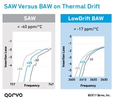 RF filters drift to the left or the right due to changes in temperature, as shown in the following SAW vs. BAW figure. These shifts can cause high insertion loss on the band edges, which could cause a low gain or POUT response from the RFFE. If the filter drifts too much (as shown in the SAW figure), then the PA pushes more power output to compensate for the insertion loss. This increases current and decreases system efficiency.
Using filters with high insertion loss can decrease linearity and increase the RF chain POUT. One big advantage of Qorvo’s LowDrift™ bulk acoustic wave (BAW) filters is their stability over temperature shifts. Diplexers, bandpass filters and coexistence filters that use BAW technology with lower temperature drift help mitigate insertion loss, and lead to good product thermals.
