


In a complex system design, power consumption of hardware components is a very important performance metric because of the resulting thermal and reliability concerns. Reducing power consumption is a challenge to system designers. Portable systems such as laptops and personal digital assistants (PDAs) draw power from batteries, so reducing power consumption extends their operating time. For desktop computers or servers, high power consumption raises the temperature and deteriorates the performance and reliability.
Measuring and controlling power consumption in a multirail supply system is always tricky for the board designer. The major tasks of measuring, controlling and indicating power consumption should be accurate, easy to accomplish, flexible and scalable depending upon the application.
Power measurement and calculation
For an effective power management and control, the first step should be to accurately measure power consumption of the system.

Power = Vsupply × Isupply
where Vsupply is the input voltage and Isupply the current drawn by the system. Voltage (Vsupply) can be easily detected by an operational amplifier or converted into digital by an analogue-to-digital converter (ADC). For measuring the current drawn by the supply (Isupply), one technique is to have a fixed resistor in series with the supply path and measure the voltage across this resistor—which is basically Ohm’s law.
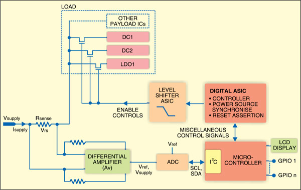
Fig. 1: A method to determine power consumption on the board
Vrs = Isupply x Rsense
where Vrs is the voltage across the resistor and Rsense the value of the series resistor that can be easily detected.
The value chosen for Rsense is very small—typically less than one ohm—in order to reduce the voltage drop and power dissipation across it. Usually, Vrs would be a small voltage that can be amplified further. A differential or an instrumentation amplifier can amplify this voltage sufficiently to measure.
Now the power is given by:
![]()
where Av is the gain of the amplifier.
A general method of measuring power consumption is shown in Fig. 1.
This method uses a differential amplifier to provide gain on Vrs. It uses a two-channel discrete ADC to convert the analogue supply voltage (Vsupply) and the amplified voltage across series resistor Rsense (Av(Vrs)) into digital quantities. The ADC resolution or the number of bits for each voltage determines the accuracy of these conversions. A microcontroller then fetches this data and performs the required actions to calculate, control and indicate power. Additional ICs may be required to enable/disable other payload ICs on the board.
The microcontroller uses the two digital inputs and calculates power by implementing a digital multiplier and divider—for basically solving the equations—through its firmware. The power control mechanism to reduce the power consumption is implemented in the microcontroller. All other routine jobs like enabling controls and reset generation are done with additional digital or analogue ASIC and some glue logic within a discrete component.
There are a number of limitations in the above approach for measuring power:
1. In a multiple-rail system, scaling up or scaling down the design, depending on the number of rails, might require a board re-spin.
2. Flexibility of user-defined actions for each supply is limited as the microcontroller cannot handle high voltages.
3. Additional discrete ICs are required for routine tasks of level-shifting, reset generation, hot-swap, etc.
4. Use of discrete components makes design less reliable and complex.
Integrated power measurement and control
Programmable logic devices (FPGAs and CPLDs) are known in the digital world for their inherent benefits like reduced design time, reprogramming and overall cost reduction. If programmable logic can accomplish board-level tasks like digital housekeeping, glue logic and power management, this can be an integrated power measurement and control function.
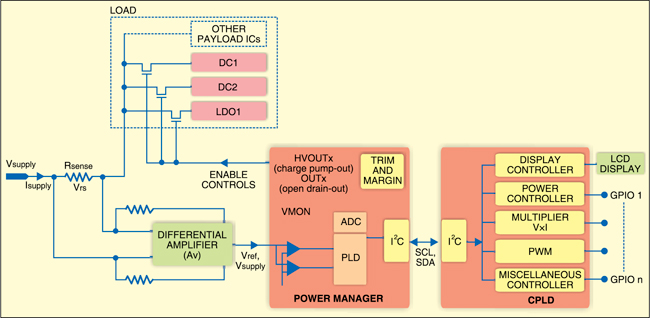
Fig. 2: Proposed solution for power management using programmable logic
For example, power management solutions are available where analogue functions are integrated with a programmable logic device. These solutions are suitable for complex power measurement and control as they overcome the limitations mentioned in the previous approach.
The power manager device is a single integrated chip that can perform voltage monitoring, sequencing and control. Its in-built 10-bit ADC converts analogue voltage into digital. An integrated I2C interface allows communication with other devices. The power manager device can provide high-voltage outputs (HVOUTs) and digital inputs/outputs—all of which can be controlled via I2C. The power manager has an integrated programmable logic device that can be programmed by software to accomplish miscellaneous tasks. The programmed file can be downloaded in the device through JTAG.
The system can use an external CPLD that has sufficient number of logic cells (LUTs) to implement a flexible and user-specific power controller function. The CPLD with built-in embedded functional blocks for I2C, SPI and timers can be used to accomplish the miscellaneous board-level tasks mentioned above. It can be programmed by JTAG or through I2C/SPI. The basic concept of such a design is shown in Fig. 2.
