Reference design for a solar breaker that can protect your PV panels in case of any fault such as over-current or short-circuit condition.
A solar breaker is a type of breaker specifically designed to protect a photovoltaic (PV) solar panel system. Solar breakers are electrical safety devices that interrupt the flow of electricity in the event of an over-current or short-circuit condition, thereby preventing damage to the system and ensuring the safety of personnel. Solar breakers are typically installed between the solar panels and the inverter in a solar power system and are rated for use in specific voltage and current ranges.

A solar breaker is a type of breaker specifically designed to protect a photovoltaic (PV) solar panel system. Solar breakers are electrical safety devices that interrupt the flow of electricity in the event of an over-current or short-circuit condition, thereby preventing damage to the system and ensuring the safety of personnel. Solar breakers are typically installed between the solar panels and the inverter in a solar power system and are rated for use in specific voltage and current ranges.
The energy tracking is supported by MCP39F511A. Power monitoring in solar installations provides multiple benefits to the customer like fault monitoring to detect a faulty inverter or panel which could cause hazardous situations and alerts in case of drop-in performance. Provision for additional safety and robustness comes from the ability to install the MCP9701, which can be used to adjust the performance due to over-temperature conditions (like disconnecting the inverter from the load in case of excessive temperature.)
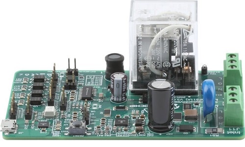
The Residential Solar Breaker Reference Design combines two functionalities: a relay driver using the HV9901 and a power monitor using the MCP39F511A. It uses the HV9901 to drive a relay which enables the user to connect/disconnect the solar inverter from the grid connection. The MCP39F511A allows the user to monitor the real-time power (both active and reactive) from the solar inverter. The power monitoring stage uses the Power Monitor Utility software for measurement through a USB connection to the board. The Power Monitor Utility software is used to calibrate and monitor the system. The software offers an automatic step-by-step calibration process that can be used to quickly calibrate power meters.
Reference Design Features:
Input Voltage: 195Vac to 264Vac
RMS Current: Up to 15A (through the relay)
External Relay Connect/Disconnect Signal
Input Power Measurement
Optically Isolated Digital signals for control and status
Application Features:
Protects solar microinverter from fluctuations in grid voltages by relay disconnect
Offers high-temperature operation with high reliability as mounted under solar panels
This reference design has been tested by Microchip. It comes with required design resources such as Gerber files, schematics, BoM, etc. You can find additional data about the reference design on the company’s website. To read more about this reference design click here.