
This automatic dual output display circuit lights up ten bulbs sequentially, first in one direction and then in the opposite direction, thus presenting a nice visual effect.
Automatic Dual Output Display Circuit
In this circuit, gates N1 and N2 form an oscillator. The output of this oscillator is used as a clock for BCD up/down counter CD4510 (IC2).
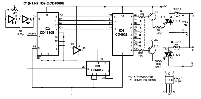
Depending on the logic state at its pin 10, the counter counts up or down. During count up operation, pin 7 of IC2 outputs an active low pulse on reaching the ninth count. Similarly, during countdown operation, you again get a low-going pulse at pin 7.

This terminal count output from pin 7, after inversion by gate N3, is connected to clock pin 14 of decade counter IC3 (CD4017) which is configured here as a toggle flip-flop by returning its Q2 output at pin 4 to reset pin 15. Thus output at pin 3 of IC3 goes to logic 1 and logic 0 state alternately at each terminal count of IC2.
Circuit operation
Initially, pin 3 (Q0) of IC3 is high and the counter is in count-up state. On reaching ninth count, pin 3 of IC3 goes low and as a result IC2 starts counting down. When the counter reaches 0 count, Q2 output of IC3 momentarily goes high to reset it, thus taking pin 3 to logic 1 state, and the cycle repeats.
The BCD outputs of IC2 are connected to 1-of-10 decoder CD4028 (IC4). During count-up operation of IC2, the outputs of IC4 go logic high sequentially from Q0 to Q9 and thus trigger the triacs and lighting bulbs 1 through 10, one after the other. Thereafter, during count-down operation of IC2, the bulbs light in the reverse order, presenting a wonderful visual effect.
The article was first published in January 2007 and has recently been updated.