


 Going up or down a staircase can be a challenging task at night, especially for kids and elderly people. This Automatic LED Staircase Light circuit lights up two LEDs, one at each end of the staircase, for a couple of minutes. The LEDs switch off automatically thereafter. The lights can be switched on from either end.
Circuit and working
The circuit diagram of staircase light is shown in Fig. 1. It is built around transistors BC547 (T1) and BC557 (T2), two 5mm white LEDs (LED1 and LED2), and few other components.
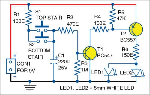
When switch S1 or S2 is pressed, capacitor C1 charges through resistor R1. This raises voltage at the base of transistor T1, which enters into saturation. Meanwhile, capacitor C1 starts discharging through resistors R2 and R3 and the base-emitter terminals of T1. Now, since T1 is conducting, the base of transistor T2 gets grounded, and hence it also starts conducting. This causes current to flow through transistor T2 and LED1 and LED2 turn on.

Since the capacitor is constantly discharging, once its voltage goes below the cut-in voltage of transistor T1, the transistor turns off, and hence T2 also turns off. This makes LED1 and LED2 switch off. The values of capacitor C1 and resistor R3 determine the discharge time of capacitor C1. So, if you want to keep the lights (LED1 and LED2) on for a longer period of time, increase the values of C1 and R3.
The switches S1 and S2 should be installed at either end of the staircase so that the lights can be switched on from either end.
This circuit works on a 9V battery/power adaptor. It can also be designed to work on 5V or 12V.
Construction and testing
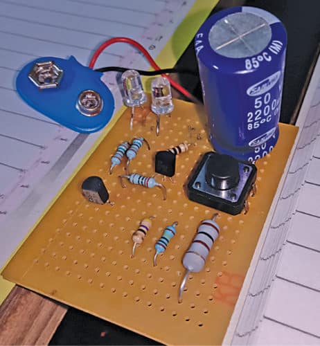
You can assemble the circuit on a breadboard and experiment with different capacitor (C1) and resistor (R3) values for proper delay time as per your requirement. Once done, solder everything onto a PCB and place the PCB inside a suitable enclosure. Extend wires of the LEDs (LED1 and LED2) and switches S1 and S2 from the PCB to appropriate locations for installation in the staircase.
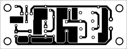
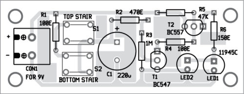
An actual-size PCB layout for the staircase light is shown in Fig. 2 and its components layout in Fig. 3. After assembling the circuit on PCB, connect a 9V DC supply across CON1.
After installation of the switches, press S1 or S2, LED1 and LED2 will glow to light up the staircase. The light turns off automatically after the preset period.
Download PCB and Component Layout PDFs: click here
The light-on duration can be extended up to 7.5 minutes by increasing the value of capacitor C1 to 2200µF. To use a higher wattage LED/LED strip-like arrangement, use transistor T2 with a higher collector current or use a power transistor.
Nikhil Shah is an electronics and telecommunication engineer with a keen interest in experimenting with electronics circuits.


Very good project
Thank You for your valuable feedback.
Dear Sirs,
is there a download link for the PCB and Components Layout?
Kind Regards
Mitsos
Please refresh the page and retry.