In the June issue, the construction of a Miniature Watch-Style FM Radio delivering stereo FM output was described. Building on that concept, the next objective was to create an even smaller FM radio compact enough to fit inside an earbud. However, the complete design proved too complex for a single article and is therefore being divided into parts.
POC Video Tutorial
This part, covering ‘Earbud-size FM radio,’ presents a simplified version—a basic FM radio embedded in an earbud with limited functionality. It allows listening to a single, preset FM channel configured on the main FM integrated circuit (IC). Alternatively, by presetting the IC to a specific frequency, the earbud can serve as a long-range FM spy device, receiving audio transmitted on that frequency.
The next part in this series of FM radio articles will introduce a tiny SMD-based microcontroller, such as the ATtiny85 or one of the world’s smallest MCUs from Texas Instruments, like the MSPM0C1104, enabling complete programmatic control of the FM radio.

The current version is a fixed-frequency FM radio earbud. The FM chip must be programmed with the desired frequency before it can be used. To allow for reconfiguration, two conductive contact points have been added to the earbud, enabling frequency adjustments when needed. For spy applications, the frequency can be matched to that of a compatible FM transmitter.
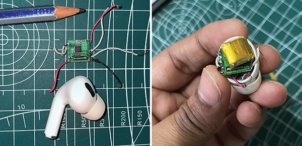
Fig. 1 shows the prototype featuring the RDA580 module. The components required to build the device are listed in the Bill of Materials table.
| Bill Of Materials | ||
| Component | Part Number | Quantity |
| A 30 to 50mAh battery used in TWS (true wireless stereo) earbuds | A compact Li-Po battery such as the EEMB LP401012, D10 KP-581013X, or a similar model | 1 |
| A 16-ohm, 7mm diameter speaker is typically used in earbuds | MACGARSEN (component manufacturer) | 1 |
| IndusBoard Coin/Arduino | Coin V2 (for programming FM CHIP) | 1 |
| RDA5807M FM Stereo Radio Module | RDA5807M | 1 |
| FM radio audio transmitter | FM wireless microphone transmitter module | 1 |
Circuit Diagram
Three different circuits are involved in this device. The first is the circuit for the RDA5807M radio IC, which must be programmed to tune to a specific FM frequency. Fig. 2 shows the circuit for programming the board to configure the FM radio frequency and volume.
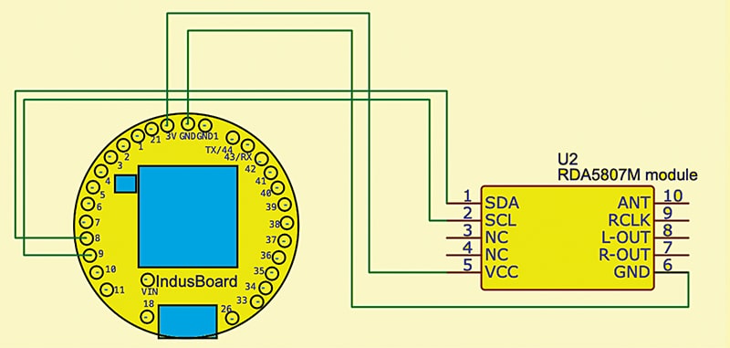
This initial programming circuit is straightforward: the IndusBoard Coin is connected to the FM chip via the I²C pins (SCL and SDA), along with power connections to GND and 3.3V. Once programmed and configured to the desired volume and frequency, the FM radio functions independently.
The next circuit is the earbud circuit, where a TWS earbud battery powers the FM chip and a 16-ohm, 7mm earbud speaker is connected to the audio output of the RDA5807M chip. All components are then installed into a standard AirPods-style case. Fig. 3 shows the earbud circuit.

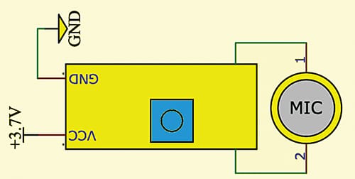
For applications requiring an FM spy device, the circuit for the FM audio transmitter is also provided. Fig. 4 shows the FM radio transmitter circuit.
Code
To configure the FM earbud, begin by setting the FM IC to the desired frequency and adjusting the volume. Connect the IC to the MCU using the SDA and SCL pins, as shown in Figs. 2 through 4. Then, install the radio library in the Arduino IDE and upload the code.
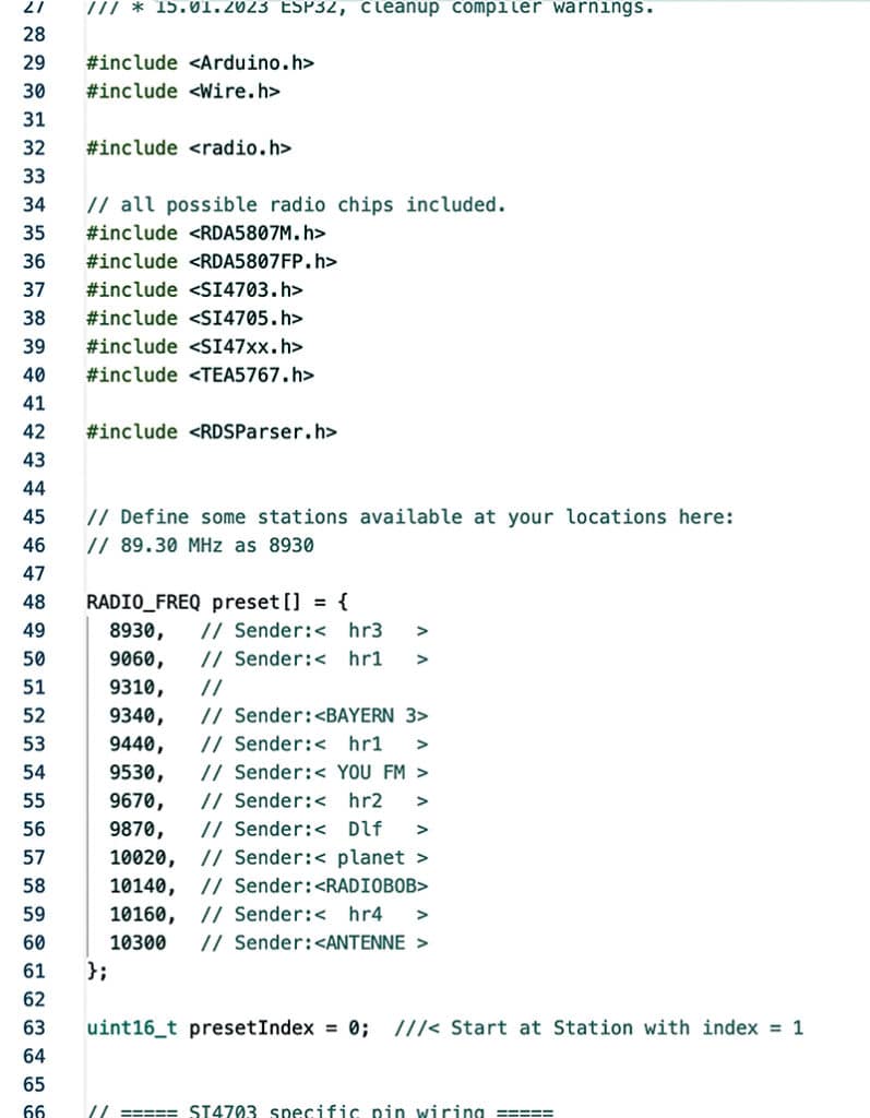
To set the radio station, send the command Fnnnnn (where nnnnn is the desired frequency) via the serial interface. Volume, bass, and other settings can also be adjusted by sending the appropriate commands. To view all available command functions, send? Help via the serial interface. Fig. 5 shows a snippet of the source code.
Construction
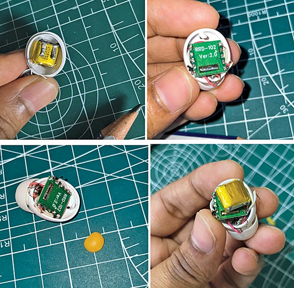
Refer to Fig. 6 before installing the battery, FM IC, and TWS earbud speaker inside the AirPods enclosure. Before configuring the frequency and volume, connect the FM radio chip to the TWS earbud speaker and battery as shown in the circuits in Figs. 2, 3, and 4.
Once assembled, the FM AirPod-style earbud is ready for use, enabling reception of radio signals on the configured frequency. For use as a spy device, connect the FM audio transmitter as illustrated in Fig. 4.
Testing
After proper installation, the FM signal can be heard at the preset frequency. To change the frequency, use the solder pads for SDA and SCL to reprogram the chip with a new configuration. Future enhancements (articles) could include the addition of a battery charging circuit or a small, side-mounted on/off switch for added convenience.
In next article on this subject, an SMD-based microcontroller (one of the world’s tiniest MCUs) will be integrated with the FM chip to create a fully functional, ultra-compact FM radio embedded within AirPods-style earbuds.