Measurement of peak level is useful while testing an amplifier or a similar device. It is handy while testing a logic circuit, as it can pick up a high transient pulse (or show that there is none) and measure an output that is swinging strongly in both directions.
The peak level monitor presented here is useful for testing amplifiers and digital circuits, or in fact anything that produces an output of about +7V to – 7V peak.

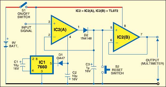
The heart of the circuit is op-amp IC TL072 (IC2(A)), which is wired as a unity-gain voltage follower with a slight difference—diode D2 on its output terminal. In a normal voltage follower, the output is directly fed back to the inverting input (–), as seen in the second voltage follower IC TL072 (IC2(B)) of this circuit.
The output of IC2(A) stabilises when the voltage at its two inputs is equal. This is when the input voltage at pin 3 equals the voltage at the cathode of D2. There is, of course, the usual voltage drop of about 0.7V across D2, but the op-amp compensates this by increasing its output voltage by 0.7V. As a result, capacitor C3 is charged to a voltage that is equal to the input voltage.
If the input voltages rise to a higher level, the voltage at the cathode of D2 rises equally, and C3 is charged to the higher level. But the reverse does not happen if the input falls. If the voltage across C3 falls, the charge has nowhere to go. It cannot pass through S2 to the 0V line because S2 is open. Neither it can pass into op-amp IC2 (B) because it is a biFET op-amp with an input resistance of 10 to 20 ohms, nor it can pass through diode D2 as it is reverse biased.
Capacitor C3 remains charged even though the input voltage has fallen. Each time the input voltage increases above its previous maximum level, the charge across C3 increases. So at any instant, C3 is charged to the maximum or the peak voltage reached. The circuit’s high input resistance means that the monitor can be used to measure the peak voltage from a source with high output resistance.
Another reason for choosing IC TL072 is its high slew rate of 13V/μs. Such a high rate means that its output is able to swing rapidly to catch sharp voltage peaks. The input offset voltage is 3 mV, which is typical of a biFET op-amp. However, this is not large enough to be of concern in this application.
IC2(B) allows measuring the voltage across C3 without letting the charge escape. It is wired as a unity gain voltage follower. The amplifier is stable with both its input voltages equal to the voltage across C3. This means that the output of IC2(B) is equal to the voltage across C3, which, in turn, is equal to the peak input voltage.
Although IC2(B) has an exceedingly high input resistance, it has a low output resistance of the order of 75 ohms like all op-amps. So it provides sufficient current to drive the multimeter without any appreciable fall in the voltage reading.
Peak-level circuits often have a high-value resistor wired across C3. This allows the charge to leak away slowly, so the output voltage eventually falls to zero. This should take five time constants, where one time constant equals RC.
With a 1μF capacitor and 1-mega ohm resistor (not shown in the circuit), RC=1, so the charge leaks away in five seconds.
This is rather too short a time for most applications, especially if the meter is digital with a relatively slow refresh rate. A 10-mega-ohm resistor (not shown in the circuit) would be better. However, reverse leakage through D2 discharges the capacitor in a reasonable time. So the resistor has been omitted. Instead, there is push button switch S2 for discharging C3 instantly whenever a new peak reading is required.
The op-amp runs off ±9V supply generated by a pair of 9V PP3 batteries. Instead of the pair of batteries, a single battery is used to provide +9V supply and a voltage inverter circuit to provide -9V supply. This costs less than the second battery and avoids the problem of one battery running out before the other.
IC 7660 (IC1) is a switched-capacitor voltage converter that produces a negative output voltage equal to the inverse of its positive supply voltage. The amount of current that it is able to supply is limited, so the negative voltage does not match the positive supply. In this circuit, it is about -8V, which is adequate for peak input voltage of up to about 7V.
Assemble the circuit on a general-purpose PCB and enclose in a suitable case. Use crocodile clips as input connectors. These can be clipped to an appropriate point in the test circuit. The output leads are terminated in 4mm banana plugs that are to be plugged into the terminals of a multimeter in place of the casual test probe.
To test the circuit, connect a 10-kilo-ohm or 100-kilo-ohm potentiometer across the 9V supply. Connect the wiper of the potentiometer to the input of the circuit. By turning the knob of the potentiometer, you can deliver to the input a voltage varying from 0V to 9V. Start with the wiper at 0V end of the track so that the circuit receives no voltage.
Connect a meter to the output and set it to the 10V or 20V scale. If you have a second meter, you can connect it to the input to monitor the input voltage. Press S2 to reset the circuit and vary the potentiometer to increase the input voltage to, say, 2V. The output should read 2V. Now decrease the input voltage to 1V. The output voltage should still read nearly 2V, though it can be seen falling slowly. Press S2 to reset the input. The output will fall to 0V but instantly rise to 1V when the button is released. Repeat for a few other voltage levels ranging from 1V to 7V to confirm that everything is working correctly.