


 Radio-frequency identification (RFID) is an automatic identification method wherein the data stored on RFID tags or transponders is remotely retrieved. The RFID tag is a device that can be attached to or incorporated into a product, animal or person for identification and tracking using radio waves. Some tags can be read from several metres away, beyond the line of sight of the reader.
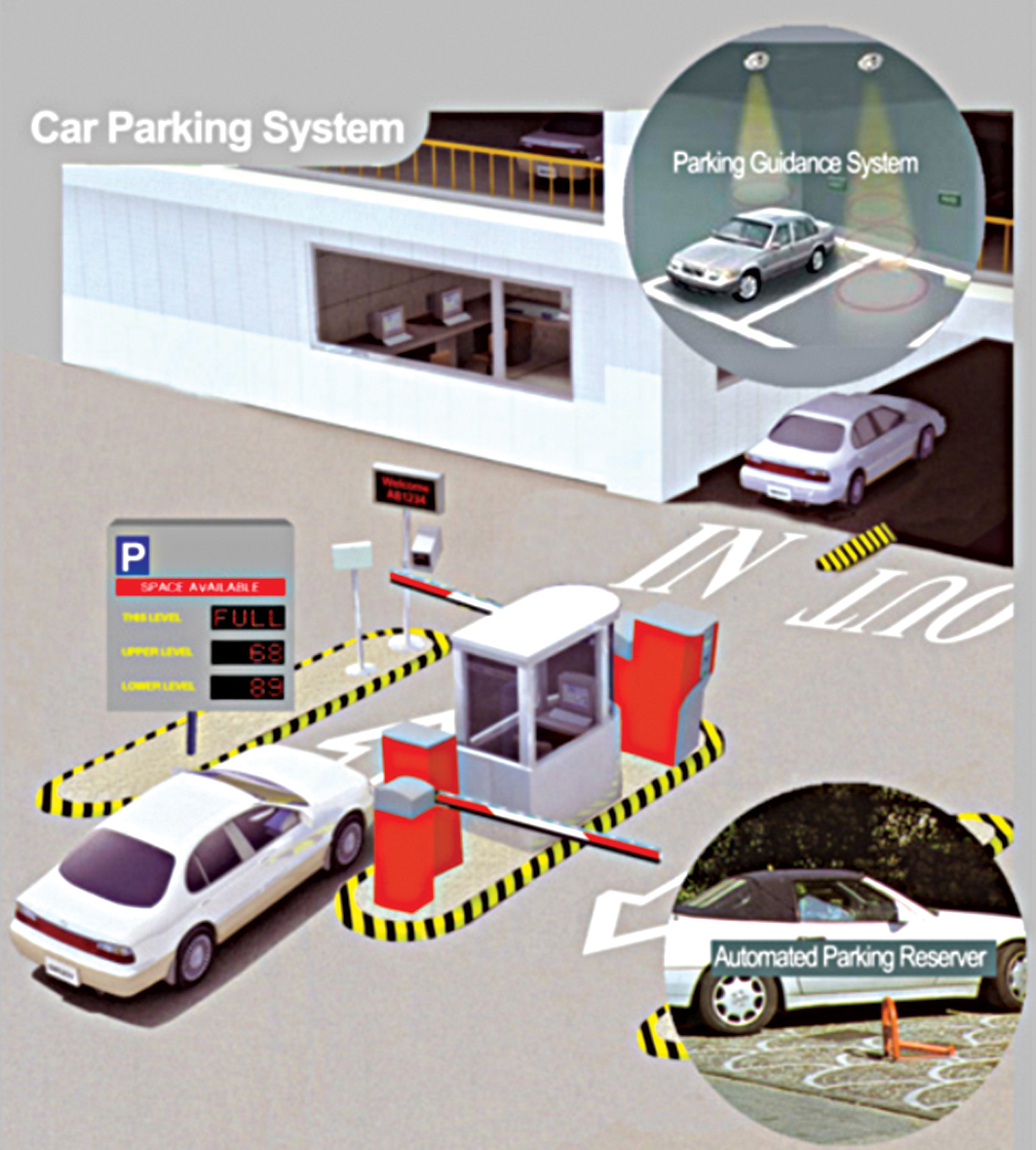
RFID technology is used in vehicle parking systems of malls and buildings (refer Fig. 1). The system normally consists of a vehicle counter, sensors, display board, gate controller, RFID tags and RFID reader. Presented here is an automatic vehicle parking system using AT89S52 microcontroller.
RFID system fundamentals
Basically, an RFID system consists of an antenna or coil, a transceiver (with decoder) and a transponder (RF tag) electronically programmed with unique information. There are many different types of RFID systems in the market. These are categorised on the basis of their frequency ranges. Some of the most commonly used RFID kits are low-frequency (30-500kHz), mid-frequency (900kHz-1500MHz) and high-frequency (2.4-2.5GHz).

RFID antenna
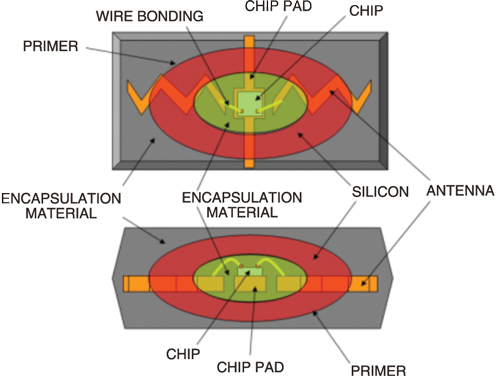
Fig. 2 shows the internal diagram of a typical RFID antenna. The antenna emits radio signals to activate the tag and read/write data from/to it. It is the conduit between the tag and the transceiver, which controls the system’s data acquisition and communication.
Antennae are available in a variety of shapes and sizes. These can be built into a door frame to receive tag data from persons or things passing through the door, or mounted on an inter-state tollbooth to monitor the traffic passing by on a freeway. The electromagnetic field produced by the antenna can be constantly present when multiple tags are expected continually. If constant interrogation is not required, a sensor device can activate the field.

Often the antenna is packaged with a transceiver and decoder to act as a reader (interrogator), which can be configured either as a handheld or a fixed-mount device. The reader emits radio waves in the range of 2.5 cm to 30 metres or more, depending upon its power output and the radio frequency used. When an RFID tag passes through the electromagnetic zone, it detects the reader’s activation signal. The reader decodes the data encoded in the tag’s integrated circuit (silicon chip) and communicates to the host computer for processing.
Tags (transponders)
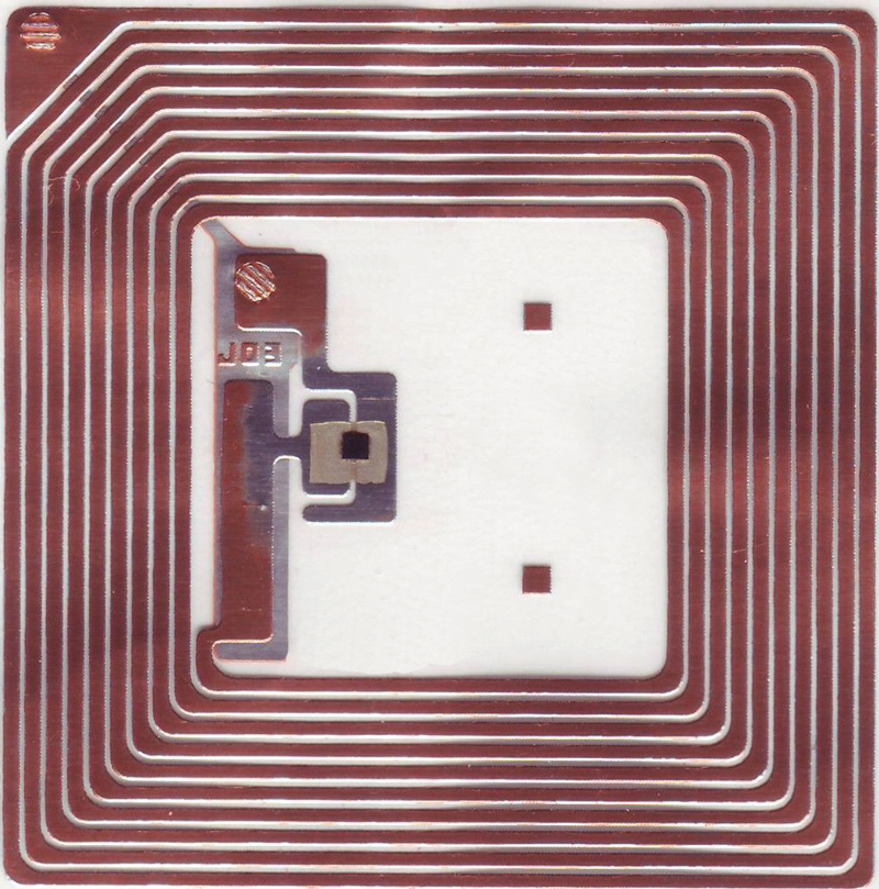
Fig. 3 shows the internal structure of a typical RFID tag. It comprises a microchip containing identifying information about the item and an antenna that transmits this data wirelessly to the reader. At its most basic, the chip contains a serialised identifier or licence plate number that uniquely identifies that item (similar to bar codes). A key difference, however, is that RFID tags have a higher data capacity than their bar code counterparts. This increases the options for the type of information that can be encoded on the tag; it may include the manufacturer’s name, batch or lot number, weight, ownership, destination and history (such as the temperature range to which an item has been exposed). In fact, an unlimited list of other types of information can be stored on RFID tags, depending on the application’s requirements.
RFID tag can be placed on individual items, cases or pallets for identification purposes, as well as fixed assets such as trailers, containers and totes. There are different types of tags with varying capabilities:
1. Read-only tags contain such data as a serialised tracking number, which is pre-written onto these by the tag manufacturer or distributor. These are generally the least expensive tags as no additional information can be included when they move through the supply chain. Any update to the information has to be maintained in the application software that tracks the stock-keeping unit’s movement and activity.
2. Write-once tags enable the user to write data once in the production or distribution process. The data may include a serial number or lot or batch number.
3. Full read-write tags allow new data to be written to the tag—even over the original data—when needed. Examples include the time and date of ownership transfer or updating the repair history of a fixed asset. While these are the most costly of the three tag types and impractical for tracking inexpensive items, future standards for electronic product codes (EPCs) appear to be headed in this direction.
Other features of the tag include
Data capacity. The capacity of data storage on a tag can vary from 16 bits to several thousand bits. Of course, the greater the storage capacity, the higher the price of the tag.
Form factor. The tag and antenna structure can come in a variety of physical form factors and can either be self-contained or embedded as part of a traditional label structure (termed as ‘smart label,’ it has the tag inside what looks like a regular bar code label).
Passive and active. Passive tags have no battery and broadcast their data only when energised by a reader. It means these must be actively polled to send information. Active tags broadcast data using their battery power. This means their read range is greater than passive tags—around 30 metres or more, versus 5 metres or less for most passive tags.
The extra capability and read range of active tags, however, come at a cost. These are several times more expensive than passive tags. Today, active tags are much more likely to be used for high-value items or fixed assets such as trailers, where the cost is minimal compared to item value and very long read ranges are required. Most traditional supply chain applications, such as the RFID-based tracking and compliance programmes emerging in the consumer goods retail chain, use the less expensive passive tags.
Frequency range
Like all wireless communications, there are a variety of frequencies or spectra through which RFID tags communicate with readers. Again, there are trade-offs among cost, performance and application requirements. For instance, low-frequency tags are cheaper than ultra-high-frequency (UHF) tags, use less power and are better able to penetrate non-metallic substances. These are ideal for scanning objects with high water content, such as fruit, at close ranges.
UHFs typically offer longer range and can transfer data faster. But these use more power and are less likely to be effective with some materials.
Electronic product code (EPC) tags. EPC is an emerging specification for RFID tags, readers and business applications. It represents a specific approach to item identification, including an emerging standard for the tags—with both the data content of the tag and open wireless communication protocols.
RF transceiver
RF transceiver is the source of RF energy used to activate and power the passive RFID tags. It may be enclosed in the same cabinet as the reader or it may be a separate piece of equipment. When provided as a separate piece of equipment, the transceiver is commonly referred to as an RF module. RF transceiver controls and modulates the radio frequencies that the antenna transmits and receives. The transceiver filters and amplifies the backscatter signal from a passive RFID tag.
How this vehicle parking system works
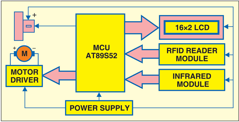
Fig. 4 shows the block diagram of the RFID based automatic vehicle parking system.
To get started with RFID based automatic vehicle parking system, the vehicle owner has to first register the vehicle with the parking owner and get the RFID tag. When the car has to be parked, the RFID tag is placed near the RFID reader, which is installed near the entry gate of the parking lot. As soon as the RFID tag is read by the reader, the system automatically deducts the specified amount from the RFID tag and the entry gate boomer opens to allow the car inside the parking area. At the same time, the parking counter increments by one. Similarly, the door is opened at the exit gate and the parking counter decremented.
The system also offers the facility to recharge the amount for each RFID tag. No manual processing is involved. In addition, the system provides security.
RFID based automatic vehicle parking system circuit
Fig. 5 shows the circuit of the RFID based automatic vehicle parking system. The circuit can be divided into different sections:
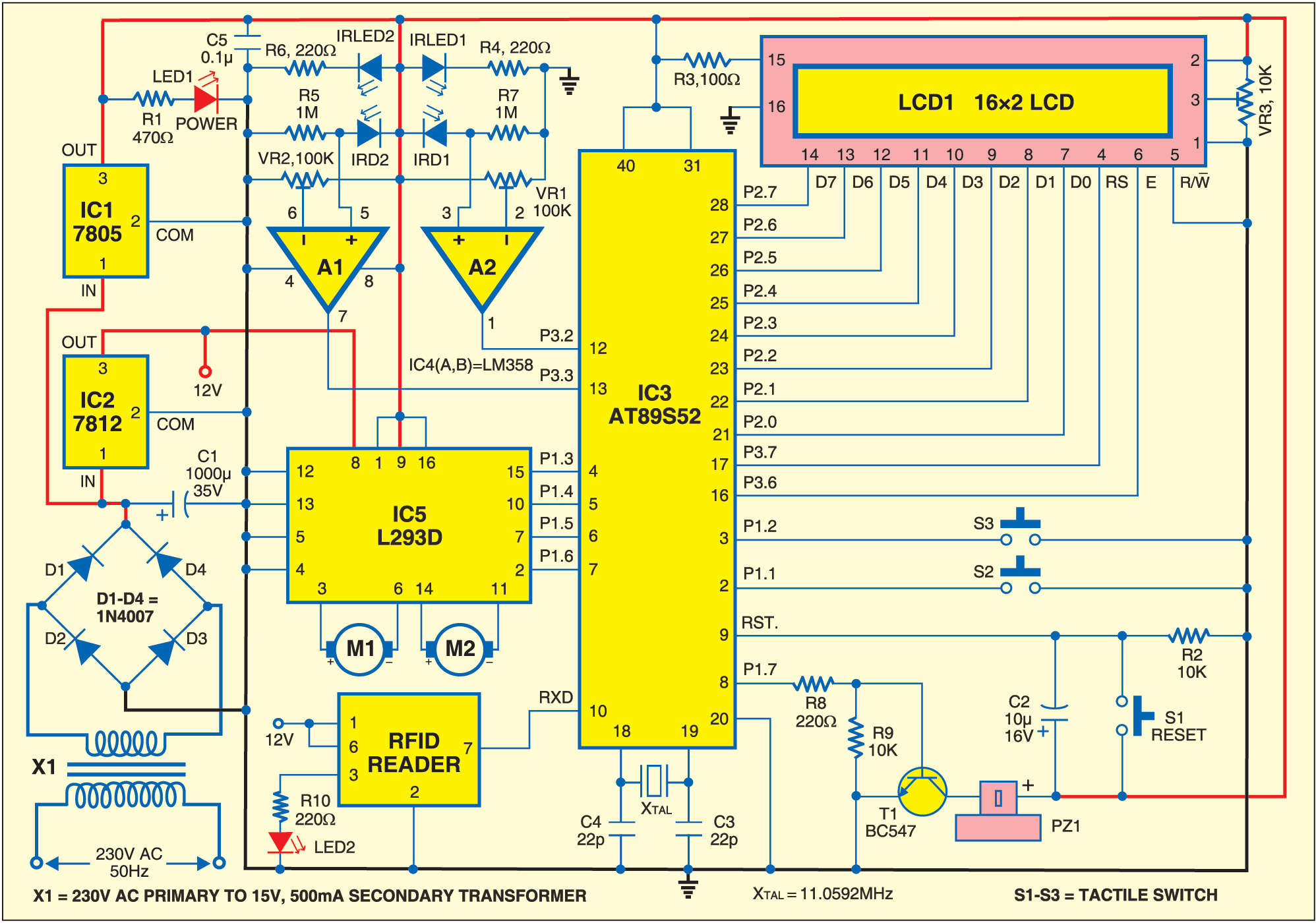
Power supply
Connector CON1 (refer Fig. 8), diodes D1 through D4, capacitor C1, and voltage regulator ICs 7805 (IC1) and 7812 (IC2) form the power supply section of the automatic vehicle parking system. CON1 is a three-pin connector that provides 15V AC or DC power supply to the circuit. In case of 15V AC, diodes D1 through D4 form a bridge rectifier to rectify the AC supply. Capacitor C1 filters out the ripples from the rectified output. ICs 7805 and 7812 provide regulated +5V and +12V, respectively, to the circuit. +5V is used to operate the microcontroller, LCD, RFID and IR sensor circuit and +12V operates the motor.
AT89S52 microcontroller
AT89S52 is a low-power, high-performance CMOS 8-bit microcontroller with 8kB Flash memory. It is compatible with the industry-standard 80C51 instruction set and pin-out. The on-chip Flash allows the program memory to be reprogrammed in-system or by a conventional non-volatile memory programmer. Other features include 256 bytes of RAM, 32 input/output lines, watchdog timer, two data pointers, three 16-bit timers/counters, a six-vector two-level interrupt architecture, a full-duplex serial port, on-chip oscillator and clock circuitry.
Connectors CON2 through CON4
CON2 and CON3 are two-pin connectors that connect the 12V DC motors to the circuit for controlling the entry and exit gate boomers. CON4 is a ten-pin dual-in-line female connector that connects the RFID reader module to the circuit.
L293D motor driver
H-bridge DC motor driver L293D (IC5) operates the DC motors to open the door or barrier for entry into and exit from the parking lot. Two high-current motor drivers can be used in place of L293D and 12V DC motors to control the entry and exit gates, respectively.
LM358 op-amp
Dual-operational amplifier LM358 (IC4) is used as a voltage comparator to compare the output of the IR sensors with a fixed threshold voltage in order to know whether the IR beam is interrupted or not.
IR transmitter and receiver
Two IR transmitter-receiver pairs are used. The IR LEDs are connected in forward-biased condition to the +5V power supply through 220-ohm resistors. These emit IR light, which is interrupted when an object comes into its way to the IR receiver. The IR receiving photodiodes are connected in reverse-biased condition to +5V power supply through 1-mega-ohm resistors. When the IR light falls on the photodiodes, their resistance changes and so does their output. This output is compared with a fixed voltage to give a digital output to the microcontroller in order to judge the entry and exit of the vehicles.
LCD display
LCD1 is a two-line, 16-character, alpha-numeric liquid crystal display. Data lines D0 through D7 of the LCD are connected to port 2 of AT89S52 (IC3). Reset (RS) and enable (E) control lines are connected to port pins P3.6 and P3.7, respectively. Control lines control data flow from the microcontroller to LCD1.
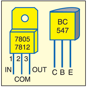
When power is switched on, LED1 glows to indicate the presence of power in the circuit and LED2 glows to indicate the presence of RFID reader. Simultaneously, the ‘Automatic RFID Car Parking’ message is displayed on LCD1 along with a short beep from piezobuzzer PZ1. Transistor BC547 drives the buzzer. Pin details of 7805, 7812 and BC547 are shown in Fig. 6.
When a car crosses the IR LED1-D1 pair installed at the entry gate, the gate boomer does not open until an RFID tag is placed near the RFID reader. After the tag is placed near the reader, the gate boomer opens for three seconds and closes automatically. If the initial recharge amount was Rs 900, the LCD display shows ‘Vehicle1 Amount’ in the first line and ‘Deducted 100’ in the second line, followed by ‘Balance Amount’ in the first line and ‘800’ in the second line. It is then followed by display of ‘Number of Cars’ in the first line and ‘001’ in the second line. If the parking lot is full, the message “Parking is Full, Sorry for Inconvenience” is displayed on LCD1.
When a car leaves the parking area and crosses the IR beam between IR LED2 and D2 at the exit gate, the vehicle count decreases by one. The LCD shows the number of cars in the parking lot along with “Thanks for Visiting” message.
Software
The program (parking.c) for the microcontroller is written in C and compiled using Keil software to generate the hex code. The program coding starts with ‘#include’ and ‘#include’ header files. The microcontroller port pins are defined using ‘sbit’ function for interfacing with the surrounding peripherals. The entry gate motor is controlled using ‘sbit START_POINT=P1^3;’ code.
The LCD is initialised using the following code:
[stextbox id=”grey”]void lcdinit(void)
{
lcdcmd(0x38);
DelayMs(250);
lcdcmd(0x0E);
DelayMs(250);
lcdcmd(0x01);
DelayMs(250);
lcdcmd(0x06);
DelayMs(250);
lcdcmd(0x80);
DelayMs(250);
}[/stextbox]
Construction and testing
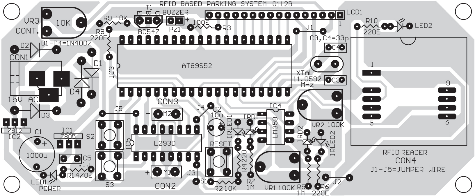
A single side PCB layout for the RFID based automatic vehicle parking system is shown in Fig. 7 and its component layout in Fig. 8. Burn the hex code into the AT89S52 microcontroller using a suitable programmer and then mount the microcontroller on the PCB. Install IR LED1-D1 pair at the entry gate such that these face each other. Similarly, install IR LED2-D2 pair at the exit gate.
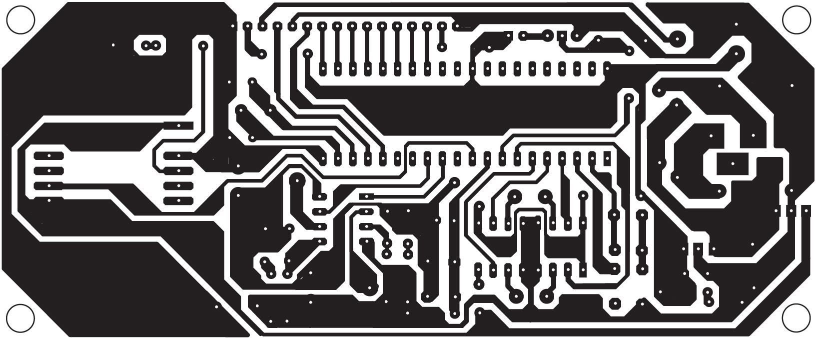
Download PCB and component layout PDFs: click here
For testing, switch on the circuit, interrupt the infrared beam between IR LED1 and IR D1 with your hand or some other opaque object and then remove it, and place the tag near the reader. The LCD should show the message as described earlier in ‘How this vehicle parking system works’ section. An amount of Rs 100 should be deducted for every interruption of the IR beam. The card can be recharged by pressing the pushbutton switches (S2 and S3) provided in the circuit. Pressing switch S2 recharges the card with Rs 900 and pressing switch S3 recharges it with Rs 500.
Similarly, interrupt the IR beam at the exit gate. LCD1 should show the number of cars in the parking lot along with ‘Thanks for Visit’ message. No amount should be deducted at the time of exit.
Download source code: click here
Feel interested? Check out other circuit projects in the circuit section.

can you please upload the source code please…
Dear maniyankal, the source code is provided within the article.
dear abhimanyu i tried the source code link but its showing page cannot be opened
Could you please check now? I have updated the link.
can i buy this project from efy?
cross questions requried regarding car parking sysytem like is there blockage of frequency??….due to some regions!!!!…….
Where to place RFID reader?Below the car as the RFID card detect it or somewhere else?
no we use rfid card like our other cards
We want to install RFID card system barrier gate of entry and exit of cars in our residential apartments in Gurgaon
Please guide us and submit quote
can I implement this with Arduino?
sir make as you above describe this project but its not working
Kindly elaborate your query.
Can you let me know about the rfid reader..like is it ttl or DB-9 socket one?
can you please upload the source code
can u pls upload the code
Hi, the source code is present on the 3rd page of the article.
may i know what programming language should i use to create something similar to this?
This project uses C programming language but you can also use other programming language including Python language.
Hello can you tell me how much expense on RFID car parking system, please
sir can u mail me the code of smart car parking system.
sir can u mail me the code of smart car parking system.
Looking for RFID based car parking systems for basement parking in condominium
You can try Arduino based RFID based automatic car parking system project available on our website at https://kitsnspares.com/. The complete kit also available