


An inverter provides power backup for mains-based appliances in the event of a power failure. Most of the inverters available in the market have complicated circuit designs and are not very economical. Some of them produce a square-wave output, which is undesirable for inductive loads.
Here, we designed a simple sine wave inverter circuit that produces 50Hz quasi-sine wave output using a single IC CD4047 and some discrete components, which makes it a very cost-effective solution.
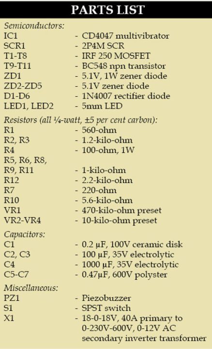
Parts Required:
Sine Wave Inverter Circuit Diagram
The DIY sine wave inverter circuit using IC 4047 is given below.

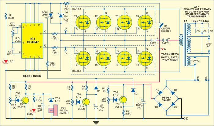
It comprises a CD4047 multivibrator (IC1), MOSFET, IRF250 MOSFETs (T1 through T8), transistors, and a few discrete components.
IC CD4047 has built-in facilities for astable and bistable multivibrators. The inverter application requires two outputs that are 180 degrees out of phase. Therefore, IC1 is wired to produce two square-wave output signals at pins 10 and 11 with 50Hz frequency, 50% duty cycle, and 180-degree phase shift. The oscillating frequency is decided by external preset VR1 and capacitor C1.
These two signals drive the two MOSFET banks (bank-1 and bank-2) alternatively. When pin 10 of IC1 is high and pin 11 low, MOSFETs of bank-1 (T1 through T4) conduct, while MOSFETs of bank-2 (T5 through T8) remain in the non-conducting state.
Therefore, a large swing of current flows through the first half of the primary winding of inverter transformer X1 and 230V AC develops across the secondary winding.
During the next half cycle, the voltage at pin 10 of IC1 goes low, while the voltage at pin 11 is high. Thus MOSFETs of bank-2 conduct, while the MOSFETs of bank-1 remain non-conducting. Therefore current flows through the other half of the primary winding and 230V AC develops across the secondary winding.
This way an alternating output voltage is obtained across the secondary winding.
The sine wave output is obtained by forming a tank circuit with the secondary winding of the inverter transformer in parallel with capacitors C5 through C7. Two 2.2µF capacitors are connected to the gates of the MOSFETs in both banks with respect to the ground if proper sinewave is not produced.
The natural frequency of the tank circuit is adjusted to 50 Hz. Current consumption with no load is only 500 mA due to the 50% duty cycle of the square-wave signal. As the load is increased, current consumption increases.
The supply voltage to IC1 is limited to 5.1 volts by using Zener ZD1 and resistor R4 with the external battery.
Low-battery Indicator Circuit
The low-battery indication circuit consists of transistor T9, preset VR2, Zener diode ZD2, resistors R5, R6, and R7, LED2, and capacitor C2. The 12V supply voltage from BATT.1 is applied to the low-battery indicator circuit with a full load (not more than 1000 watts) connected to the inverter output.
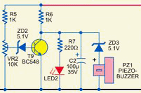
The voltage across the load is 230V AC. At this instant, adjust preset VR2 such that Zener diode ZD2 and transistor T9 conduct to drop the collector voltage to 0.7 volt keeping LED2 ‘off.’
If the supply voltage goes below 10.5 volts, the voltage across the load decreases from 230V AC to 210V AC.
At this instant, Zener diode ZD2 and transistor T9 do not conduct, and hence the collector voltage increases to about 10.5 volts and LED2 glows to indicate the low voltage of the battery.
At the same time, piezo buzzer PZ1 produces an audio tone indicating a low battery.
Low-battery Cut-off Circuit
If the battery is discharged to zero volts repeatedly, the battery life will decrease. The low-battery cut-off circuit consists of transistor T10, preset VR3, Zener diode ZD4, resistors R8 and R9, capacitor C3, and diode D1.
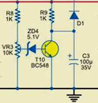
Adjust preset VR3 such that when the voltage across the load is above 200 volts, Zener diode ZD4 and transistor T10 conduct. The collector voltage of T10 is about 0.7 volts in this case and hence the SCR (SCR1) will not conduct.
But if the voltage across the load goes below 200 volts, Zener diode ZD4 and transistor T10 will not conduct and the collector voltage of T10 will increase, causing the SCR to conduct.
Once the SCR conducts, the supply voltage to IC1 (CD4047) will be 0.7 volts, due to which IC1 will be unable to produce the voltage pulses at output pins 10 and 11 and the inverter will turn off automatically. During this state, the SCR remains conducted.
The low cut-off of the inverter can be set at the load voltage of 170 volts for the tube light, fan, etc. So the tube light and fan will not be switched off until the voltage goes below 170 volts.
No-load Cut-off Circuit
If there is no load connected to the output of the inverter, the output voltage is 270 to 290 volts. This voltage is sensed by the 0-12V tap at the secondary winding of inverter transformer X1, which is connected to the no-load cut-off circuit comprising Zener diode ZD5, transistor T11, preset VR4, resistors R12 and R11, and capacitor C4.
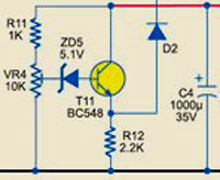
When no load is connected, the voltage at the 12V tap will also increase. This voltage is rectified by the full-wave bridge rectifier comprising diodes D3 through D6, filtered by capacitor C4 and given to transistor T11.
Adjust preset VR4 such that if the inverter voltage goes above 250 volts, Zener diode ZD5 and transistor T11 conduct. This increases the emitter voltage, hence the SCR fires to switch the inverter ‘off.’ When a proper load is connected, the inverter will automatically turn on.
Sine Wave Inverter PCB Design
An actual-size, single-side PCB for the pure sine wave inverter circuit is shown below.
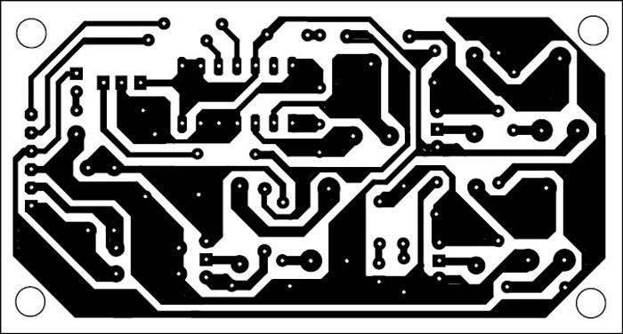
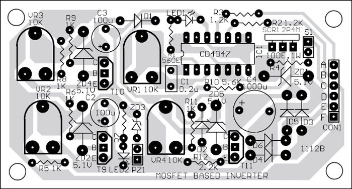
A suitable connector CON1 is provided on the PCB to connect the MOSFET banks and the transformer externally. Connector CON1 pins A through F are also marked on the schematic.
Assemble the circuit on a PCB as it saves time and minimizes assembly errors. Carefully assemble the components and double-check for any overlooked errors. MOSFETs should be mounted over heat sinks using mica spacers as the insulators between them.
Download PCB and Component Layout PDFs
Connect the 24V supply terminal directly to the center tap of the primary winding of the inverter transformer, which carries a maximum current of more than 50 amperes with 1000 watts.
The current depends on the load applied. There is no need to add a switch in the high-current path to make the inverter turn on and off. The inverter can be switched on and off by low-current switch S1.
You can check the other inverter circuits below:
About Author:
Dr. R.V. Dhekale: He is an associate professor and head of the Department of Physics, Kisan Veer Mahavidyalaya, Wai, District Satara, Maharashtra.
The article was first published on 27 March 2016 and was recently updated on 16 November 2025.


hi, nice post. pls i want to know how i can increase the capacity of the inverter and also how i can calculate the load that is run on the inverter. thanks
If change the rating of transformer,can I use the same circuit?
Here is the reply from Dr. R. V. Dhekale to nmaemeka.
Power of the inverter can be increased by increasing battery voltage by connecting batteries in in series accordingly inverter transformer design should be changed. Because power of the inverter is given by P= I x V, where I be the primary current and V be the primary voltage of the inverter transformer. Power can be increased by increasing the current flowing through the primary of the transformer keeping the voltage constant. For that primary current and voltage of the transformer should be changed accordingly. If current increased accordingly no. of MOSFETs in two channels should be increased otherwise MOSFETs may be damaged.
how modifi out for 60 hz
Please elaborate your query.
au québec nous avons du 220volt 60 hz et non 50 hz comment peut ton modifier la sortie de linverter s.v.p.?
Kindly write your query in English please.
Hello, how can you change the output frequency of the inverter in 240 volts 60 hz for québec instead of 50 hz
just varry the potentiometer and get an oscilloscope to check the frequency..here the potentiometer is VR1
Adjusting VR1 may affect the duty cycle so I don’t think it is this simple. Changing the resistance may require changing C1 to keep a 50% cycle, I’m not positive on that. Either way an Oscilloscope is required to get the circuit tuned properly because there are always tolerances in components even if very small.
Sir,
If I change 18-0-18volt 40 Ams Transformer to 12-0-12 volt 30 ams Transformer on this circuits can it work on 12volt battery or can made any changes for 12 volt battery please advice.
Regards,
Santosh
sir upper circuits can it work on 12 volt battery also if not please advice what can made changes required
does this inverter only work using a 180A batteries? can it work using for example 40A batteries ??
and also what is the relation between the primary winding voltage (here 18-0-18) and the battery voltage (here 24 v ) ?
this circuit looks great, can the power be increased to 5KVA
how to the power be increas to 5KVA
is the PCB layout which is given is correct because I find that more components given in the component list are missing
The given PCB layout is correct. Yes, some components including transformers, Mosfets, etc will not be seen, because they are not to be mounted on the PCB.
sir can i use same circuit for 12v other AH rating battery???
Here is the reply from Dr. R. V. Dhekale: Yes, you can use batteries of 12V, 24V, 48V ……etc to get more power output. You have to be careful for providing 12V taping for the circuit. Accordingly, you will have to change the specifications of the inverter transformer.
Hello, how can you change the output frequency of the inverter in 240 volts 60 hz for québec instead of 50 hz
Here is the reply from author Dr. R. V. Dhekale: Frequency can be changed from 50Hz to 60Hz by the use of the preset provided.
“When proper load is connected, the inverter will automatically turn on.”please explain how .also it is hard to believe that the output will remain sinusoidal in varying load and high o/p current condition.I guess you are from shivaji uni M.Sc.1981 batch.if yes then you would remember me.
Here’s the reply from author Dr. R. V. Dhekale. “Thank you Sutar Sir for showing interest in my article. I got sir, I am your student in 1981. Explaination: When load is not connected, Outpu AC voltage is high as 270 volts for the fraction of second. This voltage is steped down and rectified and given to the one of the transistor which will drive the SCR at perticular position of thr preset so SCR will be in latched state so voltage to the IC is decreased to 0.7 volt. Hence no pulses are produced threrefore inverter becomes in off state. I have used resistive load so sinewave is produced for varing load. By the use of inductive load shape of waveform can be changed.”
What about inductive load? I want to drive my motor 0.5hp from this.
Will this inverter not work properly?
If change in rating of transformer 12-0-12 volt what Chang in this ckt.
Hello, could You please give us detailed info regarding wire size inside primary and especially secondary coils.
I presume that “main” secondary coil is 230V and that wire in that part of wnding is not the same width like the rest of that coil up to 600V or maybe it is all the same wire ? It is not usually found 600V in any transformer and that is jus for what ? to suppres higher harmonics in order to obtain sinusiodal output ?
Can i place those capacitances at the 230V coil ?
Also, in order to easily construct this inverter from existing parts, is it possible to replace secondary winding with 12V with another transformer 230V/12 (Connected to the secondary (output) 230V.) which is laying around ?
Any revision for 60hz?
Why 4 MOSFET are use instead of usiing 3 MOSFET in both the banks
to get more power out of the system
Can you give me the parameters of the components correctly?
Can tell me exactly the details of the components are not. Irf 250 mosfet has many types
Hi ! This is a very good circuit but please explain how it charges the battery when power is available.
Can i get this printed board and components .Where i can buy.?
Iwant to buy the pcb and components please help me
Can you provide me the component and PCB for the project Electronics Projects: 1kW Sine Wave Invert on Payment basis
Tanking you
Arvind thulasidas
The component and PCB layout is already present within the article.
Dear sir i need to do this project for my home .So kindly give me Gerber format file of this PCB and kindly share the size of the board to print.or else to guide ,where i can buy this kits with all items .Plz kindly help me.my mail [email protected]
Where i can buy this board with all items and transformers
@ Thanga Pandiyan, you can buy the components from shopping.kitsnspares.com
Nice tutorial, pls can u show circuit diagram of automatic battery charger that is compatible with the circuit
Comment:pls sir I need to know about the inverter transformer winding, how many turns at the secondary and at the primary side and that of the overload, is that a different transformer? pls explain more.
i want to make an inverter for my home.can i make one using this circuit.will you help me through it
how to the power be increased to 5KVA our circuit
Kindly elaborate your query.
Why 4 MOSFET are use instead of usiing banks pls
Kindly elaborate your query.
Comment: Halo Sir, Thanks for giving a very wonderful circuit. From my observation, the transformer turns for the tank circuit looks to be different from the o/p turns, in fact it looks to be an extension, can you elaborate on the turns ratio between them?
The author Dr R.V. Dhekale replies: Thank you Sukura sir for showing the interest in my article.
I don’t know the number of turns of primary and secondary. I had given detail of the transformer giving primary current and voltage and secondary voltages. Manufacturer has to decide how many turns in primary and secondary should be. But if you give the specifications of the transformer to manufacturer, he can provide the information you want.
is this a pure sine wave inverter
HOW TO CHARGE THIS BATTERY
Comment: if tis inverter is used to load 0.5hp(373watts), its work r not? plz reply
Comment: if tis inverter is used to load 0.5hp(373watts) Ac motor, its work r not? plz reply
Hello EFY…. I am working on this circuit, is its output is good for tv and laptop, if not then please guide me to make it preferable for tv, laptop or another electronics devices.
Thanks and regards from Punjab….
Hello, this is not a sinewave inverter, just a poor inverter rectangular without sinewave… and without regulation output…
If you like your TV, don’t connect this gadget!
It’s a shame to post this horror…
Hello Li4Ti5O12,I suppose you have already tested this circuit, please I would like to what your findings were, thanks in advance.
Comment:Hello sir,I commend your effort for presenting this project and the fact remain that you still need to guide the young ones on how to go about the principle of widing the transformer as l can see that it is this transformer setup that would form the heart of the project, l am still thinking that your professor during your 1980 batch will be intrested at your success,
The author Dr R.V. Dhekale replies: Thank you Lawrence Ajimoti for showing the interest in my article. You may contact to any transformer manufacturer and ask him to specifications of the transformer given. If not, some transformers are available with me.
Hello sir, Solar to 2Kva used inverter circuit post sir.
sir in inverter at home we use a single battery of 40Ah. why we are using two battries hare…??
is it not bulky and cost effective using 180Ah..please reply soon
Dear Sir,
My question is: In case low battery indicator ckt
when battery is full charged then ZD2 and T9 conduct then LED will be off but all charge will goes to ground through T9. After battery will again discharged.
I am confujed please reply sir.
Thank you.
Please I just need to know if these inverter battery is power by 12v/180ah battery or 24v/180ah battery.so I’m confused if the battery is a 12v battery those that mean the positive terminal of the battery is going to the centre tap of the transformer and the negative terminal of the battery is going to the source of the MOSFET.please I just need explanation on how a table battery can be connected to the circuit.
Hello sir the ABCDEF part will all b joint together please I need more explanation. My mail is [email protected].
Love to hear from you
Hello Sir, Please add the programmed of this IC’s (Code)
There is no program, Rahmat. There are no microprocessors here.
This is not a sine wave inverter
Kindly elaborate your query.
The out put of inverter would be square wave and not sine wave .Why the title of article is “1kW Sine Wave Inverter” ,which should have been “1kW Square Wave Inverter”
Sir i have don this project when i connect to battery its getting short
What i have to do
Please replay sir
I use the same ic4047 for 1kv it’s work but not as much efficiency its helpful for my diploma project
Sir, Please.Can be use only one batterty ?
Can you elaborate briefly how occurred sine wave or inverted signal from gate signals from ic1 to MOSFETs banks?
Sir, please how we we recharge the battery Wen it goes low and prevent over charging?
Also I don’t get y the the Low Battery and battery cut off circuit are talking from a single battery 12v whence our circuit is running on 24v.
Can you give knowledge on 3 Phase Diode Clamped Multilevel Inverter to drive a 3 Phase Induction Motor ?
Hello sir, can i use this inverter with 35ah / 40ah car battery?
Is this perfect sine wave 1kv inverter circuit for tv’s laptops or any indactive loads?
Hello Sir, The input/output port labelled A, B, C, D, E, F were not labelled. Can i get them? Thank You Sir
Thanks.very good text.What is the difference between IGBT inverters and MOSFET inverters?
Sir,
How can we get or make this kind of transformer? Or is the any way to buy this
ABCDEF for what i/p or 9/p.. can we chan^e transformer rating ? can we use only one 12 V , 150 AH battery ? Heat sink size ?
thank you for article is very good
You are most welcome.
Thank you so much sir for this post.
How can i use a transistorized astable multivibrator instead of the IC.
Thanks.
Tell me the labels ABCDEF. and where to connect them. Also is both the inverter circuit and battery indicator in that PCB Layout
The schematic shows terminals A, B, C, D, E and F, what are connected to these terminals?
Today, with solar power available, we must provide intelligent load switching to balance input with output to keep the battery potential at 12.5v during operation. For this relays supply loads of 40, 80, 160, 320, and 640 watt packs and these relays are energized in a sequential binary manner so that the output goes up or down in steps of 40 watts when input solar power goes up or down respectively, thus balancing the power on both sides.
Comment:is the transformer in the circuit two different ones.pls if there are how can I connect them.am really in need of your answer
Pls sir is the transformer in the circuit two different transformer,if yes,pls how can I connect it.am really in need of your answer
Can any one please explain how the inverter will automatically turn on when proper load is connected after No_load cut off, since the SCR is in fired state to switch the inverter ‘off.’ How the SCR will turn off in order to to resume oscillation when proper load connected.
The transformer does not look like it can be purchased “off the shelf”. Where can this transformer be found?
Thanks for this Sir.
Please Sir, I’m unable to get the SCR 2P4M, what can be used to replace this SCR?
Awaiting your response sir. Thanks.
SN102, TIC206D, BT169, TYN604, 2N1596, 2N1595
I also couldn’t find it but At least this is working for me
Please remember to flip the pcb when printing
The problem here is the voltage across C5-C7 which is never explained…. What is the voltage across C5-C7?
I will try to appy the theory then i will be back for feedback
Hi,
Interesting inverter. But where is the feedback circuit?
I want to build a 3kva inverter using irf3205. Can I use this generator/ oscillating circuit to drive the mosfet?
Thank you so much sir for this post.
How can i use a transistorized astable multivibrator instead of the IC.
can anyone pls tell me, how do i design this circuit in KiCad?
You can design it using Kicad but you may not be able to design exactly like the one shown here. This circuit was a customised design using very old Protel software.
Gentlemen Good Morning from a far South Africa. I am using a Hoffmann 900w inverter for my camping/SUV setup. Using it at least 6 months every year. During recent 360v surge from Escom i don’t get any direct ac from the inverter. It only works when the battery is connected. It also won’t charge the battery.
My problem is that This inverter was discontinued years back and i can’t anybody that is willing or able to help me without huge expenses which i cannot afford.
My question is looking at the circuit i like very much but:
Can a change over circuit be added?
Can a battery charhing circuit be added whenever connected to supply?
From a expense view why not only 1X 12v say 105ah battery?
I am already 81yrs old but still enjoy your website very much.
Regards and have a nice day.
Schalk
Explain the natural sine wave once again..
Good day sir, can the oscillating circuit drive igbt and can I increase the frequency to 25khz
Hello sir, i have question, what is low current switch, can you please explain and sent us example or image?
thank you in advance
There are many low current switches available in the market including toggle and slide switches with current ratings between 1A and 5A
How is it produces sine wave?
I think it is square wave.
Please explain me is it really sine wave.
The circuit produces quasi sinewave output. All the details are explained in the article above. Please go through the article once again
As far we know when want to make sine wave out put then transformer battery side should be two (2) terminals.
And proper microcontroller based program only can produce near about sine wave frequency.
So my question is how you have described here with the help of c5 to c7. Makes it’s sine wave?
Another question is you mentioned mosfet gate connected with capacitor but in the schematic design it’s not showing.
Please describe me.
what i have done . i only need a inveter part of circuit. low voltage indicator else are not required.plz help me about this issue
You can use the inverter circuit section only without the indication circuitry. But we recommend to use the complete circuit as shown.
1 can i use a 12 0 12 transformer to run this circuit? 2 in the absence of 0-12v at my transformer out put, what other power can i use to operate the no load cut off? Thanks.
HI GUYS,HOW ARE YOU? I WILLING TO MAKE 1kW Sine Wave Inverter.BUT THERE IS NO INFORMATION ABOUT TRANSFORMER( X1). CAN YOU EXPLAIN COMPLETELY, HOW I CAN MAKE THIS TRANSFORMER AT HOME???
DO YOU HAVE BIGGER WATT INVERTER( LIKE 10.000W OR SO)???
THANKS FOR YOUR CONCERN.PLEASE RELAY AS SOON AS POSSIBLE.
what i have done . i only need a inveter part of circuit. low voltage indicator else are not required.plz help me about this issue
Very Nice Project. I love this good and perfect circuit. Thanks again
Thank you for your feedback.
construction of smart inverter change over printed circuit board (PCB).
Need one with dis project
Call me 09077776426
hi!
Where i can buy this board with all items and transformers
HI
What the power in va for 600v in secondary transformer or just 600v in very low milliampers
best regards
Dear Dato,
For calculating inverter’s power, you have to mention current also. Power of the inverter is given by P= I x V, where I is the primary current and V be the primary voltage of the inverter transformer. And also need power factor.
Most inverters have the efficiency (power factor) range from 60 % to 80%. Power factor of an inverter is the ratio of power required by the appliances to power supplied by an inverter. Power factor of most inverters ranges from 0.6 to 0.8.
Regards
Hi,
what are connected to these terminals?
What is the THD of the output?
THD stands for Total Harmonic Distortion, and it is a measure of the amount of harmonic distortion present in a signal compared to its original frequency. It can be calculated for various signals, such as audio signals, power signals, or any other periodic signal.
In an inverter, the THD of the output signal can vary depending on the type of inverter and the load being driven by the inverter. In general, the output waveform of an inverter is a pulse-width modulated (PWM) signal, which is a series of low and high voltage pulses within the a frequency range of inverter.
The THD of the output waveform can be affected by various factors such as the switching frequency of the inverter, the shape of the output waveform, and the type of load being driven. In general, the THD of an inverter output waveform should be as low as possible to ensure proper operation of the load and to minimize electromagnetic interference.
To measure the THD of an inverter output waveform, a distortion analyzer or a spectrum analyzer can be used. The THD is typically expressed as a percentage and is calculated by measuring the total harmonic content of the waveform and dividing it by the amplitude of the fundamental frequency. A low THD value indicates a clean output waveform with little distortion, while a high THD value indicates a waveform with significant harmonic distortion.
Thanks.very good text.What is the difference between IGBT inverters and MOSFET inverters?
Hello Sir, The input/output port labelled A, B, C, D, E, F were not labelled. Can i get them? Thank You Sir
Refer circuit diagram and PCB carefully.
All the lebels are mentioned in circuit as well as in PCB
(refer CON1 in PCB where A,B,C,D,E and F are clearly marked)
hi, someone gave me this circuit to build, i followed the schmatics and details from the writeup,
there is no output or oscilation, please help me
To check the oscillations, first of all wired IC1 and associated components.Because IC1 is wired to produce two square-wave output signals at pins 10 and 11 with 50Hz frequency. The oscillating frequency is decided by external preset VR1 and capacitor C1.You can vary the VR1 and check frequencis at pin 10 or 11 or at point A or B using a oscilloscope. it should be 50Hz.
I have built this circuit without the charging system. But always some of the mosfets are burnt. And suggest it is due to back-emf of the transformer. What is the best way to protect the mosfets from damage?