


 The most essential tool for engineers is a logic analyzer, which they operate using a laptop or PC to show the results. A stand-alone analyzer with a display can cost you around 10 thousand rupees or more. So, today we will design a low-cost logic analyzer that has its own stand-alone display that is portable and can be carried in the pocket. Hence, do your design and use this tool without worrying about the laptop or PC for viewing the data. The device can be designed by configuring the following components.
Bill Of Materials
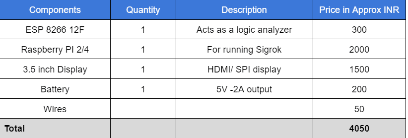
Note: The display part is optional and attachable like an accessory. Hence, if you want to remove the display, then the ESP is itself a logic analyzer, and further, to check real-time data on a PC, install the Sigrok. It will cost you only INR 350 if you detach the display.

Coding
For the logic analyzer, we program the ESP 8266. Hence, it acts as a USB logic analyzer. We can connect the circuit or device’s output pins to the ESP GPIO, which acts as a channel for the logic analyzer. For that, we need to install the analyzer library. Open the Arduino IDE and then go to Sketch and Clock. Add the library using zip. Now add the analyzer library by selecting the zip file of the library. Download the library using the following link.
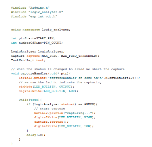
Now we can code the analyzer. Open the Arduino IDE and then select the ESP logic analyzer example code. Now in the code, we can set up frequency, baud rate, and other configurations.
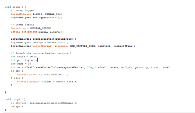
Now we need to select the right port number and the right ESP8266 board and upload the code.
Connection
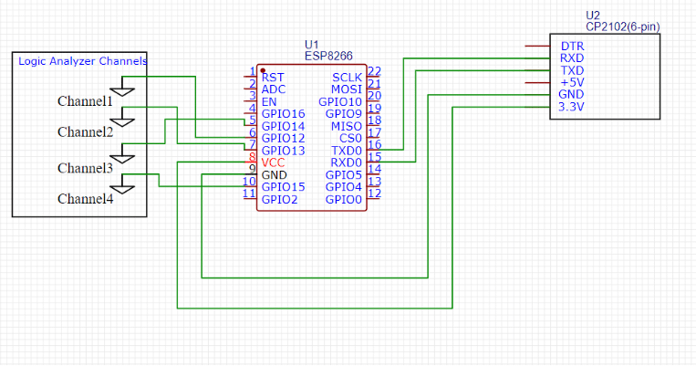
Now connect the FTDI and channel GPI as follows. The Logic analyzer channel GPIO are 13 to 16
Now our analyzer is ready, but our device can capture the logic data using GPIO pins, which act as a channel for the analyzer, but we can’t view it without any software, so if you have a PC or laptop, then install the Sigrok using the following link.
https://sigrok.org/wiki/Main_Page
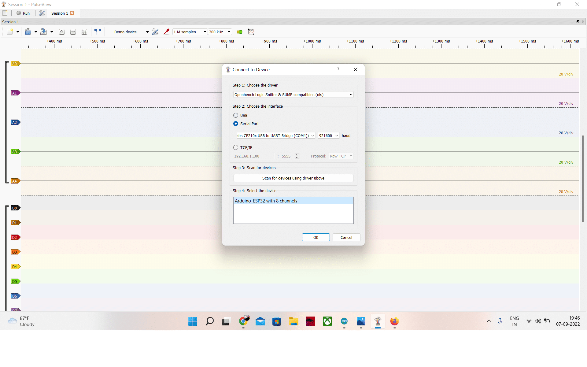
Now open the Sigrok Pulseview and then go to connect and select the Open Bench logic snipper. Now, select the serial port and baud rate and then scan for the device. After scanning, you will receive the name of the analyzer device. The name used for this device is the ESP board. It shows ARDUINO ESP with 8 channels. Select it, and now your 4-channel logic analyzer is ready.
Develop a Portable Display
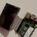
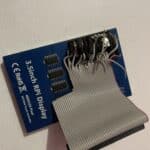
Now, to make the device a standalone analyzer that needs no laptop or PC, develop a small data displaying device that is portable and small enough to be carried anywhere. Install the latest OS on the Raspberry Pi, then install the SIGROK Pulseview on Raspbian OS, and set up the display driver. If you are using an HDMI display, then you do not need any drivers, but if you are using an SPI display, then install the display driver. Every display consists of its own driver and varies with display type. Hence, follow the respective instructions for the driver provided. Now connect the female GPIO of the display to the Raspberry Pi’s male GPIO, aligning it in line. If you do not have the female GPIO on the Raspberry Pi display but only have male pins, then cut the female GPIO extender of the Raspberry and connect the wires to the display pins. Then connect the end of the female GPIO to the Raspberry Pi as in the pic below . Then fix all the components.
Testing
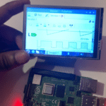
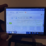
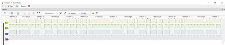
Now the device is ready, power the raspberry pi with 5V and insert the ESP USB into the Raspberry Pi. Now, open the Pulseview and select the ESP device, and connect it as a analyzer. The ESP pins can be used as a channel for the analyzer; connect it to the pins for doing signal analysis. The signal analysis can be seen on the display connected.
