 This Device Controller project based on an 8-bit ATmega328P microcontroller (MCU) can control up to eight devices connected to its electromagnetic relays. The article also describes how to program an MCU to accept infrared (IR) remote control signals for controlling the relays.
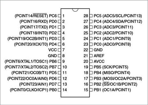
Here, an ordinary TV remote control is used along with the 28-pin ATmega328P MCU in DIL package and Arduino bootloader to control the devices. Pin details of ATmega328P are given in Fig. 1.
Circuit and working
Block diagram of the project is shown in Fig. 2 and its complete circuit diagram is shown in Fig. 3. To understand the project, it is divided into following four sections:
- Power supply unit
- Infrared light receiver unit
- Microcontroller unit and its programming
- Relay driver output and power isolator unit


Power supply unit
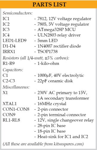
This section includes a 230V AC primary to 15V, 1A secondary step-down transformer (X1). The secondary of this transformer is connected to a bridge rectifier circuit formed by four IN4007 rectifier diodes (D1 to D4) and filter capacitor C1. Regulators 7812 (IC1) and 7805 (IC2) are used to get required 12V and 5V supplies, respectively.
Infrared light receiver unit
An IR module TSOP1738 (IRRX1) is used to receive infrared light signal from any TV IR remote control. The IR remote control signals are sent to IC3 microcontroller’s pin 18 for processing and controlling the relays as per program and calibration of the controller unit.
Microcontroller unit and programming
This unit is the heart of the device. It has two parts: hardware and software.
The hardware receives the infrared light’s hex-coded signals generated by TV remote control and sends them to the MCU through infrared receiver module TSOP1738 (IRRX1).
Output pin 3 of IRRX1 is connected to MCU’s pin 18. The MCU’s output pins are programmed to turn on or turn off using IR remote input signal. MCU’s output pins 4, 5, 6, 11, 12, 13, 14 and 15 are connected to pins 1 through 8 of ULN2803 (IC4) relay driver unit. The output pins 18 through 11 of IC4 are connected to RL1 through RL8 relays, respectively as shown in Fig. 3.
The MCU can be programmed by following the steps below:
- 1. Download Arduino IDE software and install it in the PC
- 2. Connect USB cable between Arduino board and the PC
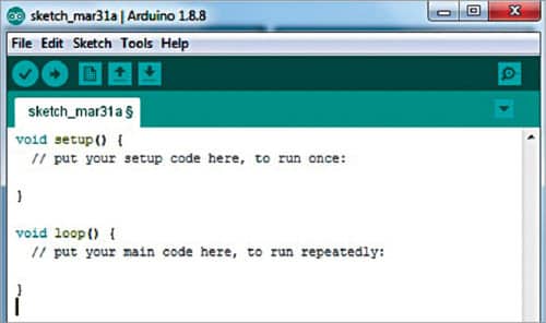
- 3. Open Arduino IDE by clicking the Arduino icon from Desktop. (You will get Arduino programming/sketch window as shown in Fig. 4.)
After installing Arduino IDE in the PC, install IR remote libraries. For this use IRremote-2.0.1 and IRremote-2.2.3 folders included in this project. Copy these folders under Arduino/Libraries in a Windows PC. Alternatively, you can install the libraries from Arduino IDE as explained below:
- 1. Select Sketch->Include Library->Manage Libraries option
- 2. Type IR Remote and press Enter
- 3. Select IR Remote (By Cristiano Borges) and click on Install. (This will install all IR libraries in Arduino IDE software.)
Decoding IR remote
Every remote has a different code corresponding to each key/button. In order to use your IR remote in this project, you need to decode the code of each button. For that, first open the IR decode.ino code from the Arduino sketch window.
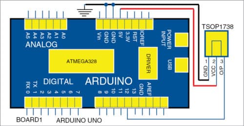
To use this code you need a hardware circuit such as the one shown in Fig. 5. Here, output pin 3 of TSOP1738 module is connected to pin 12 of Arduino Uno.
Compile the code and upload it to Arduino Uno board. Point the IR remote towards the TSO1738 module and press any button on the IR remote. You can see the decoded value of each button on serial monitor of Arduino IDE. (Please note, the decoded values may differ from remote to remote.)
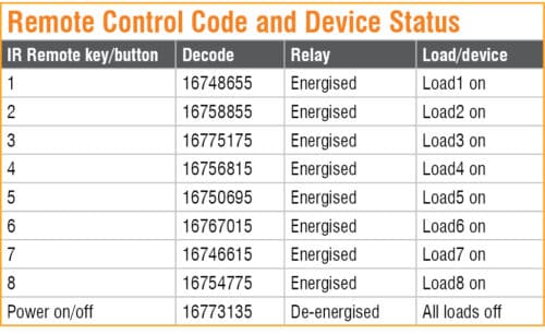
The decoded values observed during testing are listed in Table 1. You should use these decoded values in your final Arduino code (devicecontefylab.ino). After entering the decoded value of each key in the final code, compile it and upload it to the Arduino Uno board. Then remove the ATemga328P MCU from Arduino Uno board and use it in the main device control circuit as shown in Fig. 3.
Relay driver and power isolator unit
This section includes ULN2803 (IC4) relay driver, which is used to drive the relays as well as to isolate low-voltage section of the circuit from high-voltage section. Basically, it is used for switching on or switching off a high-voltage device connected through a set of relay contacts.
Construction and testing
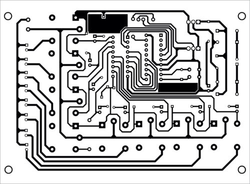
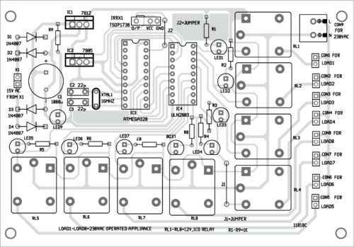
A PCB layout for device controller is shown in Fig. 6 and its components layout in Fig. 7.
Download PCB and Component layout PDFs: click here
Download Source Folder
First, decode each key of the remote control, include decoded values in devicecontefylab.ino code and upload it to the MCU as explained earlier. Remove the MCU from Arduino board and insert it into the PCB. It is recommended to use a 28-pin IC socket for the MCU.
Connect eight loads across Load1 through Load8. Connect secondary of transformer X1 to the PCB for power supply. Point the IR remote towards TSOP1738 module from a distance of about one metre.
When you press a button of the remote, say key 1, relay RL1 energises and Load1 turns on. When you press power on/off key of remote control, relay RL1 de-energises and Load1 turns off. Similarly, you can operate the remaining loads by pressing remote buttons 2 through 8 as listed in the Table.
Adeeb Raza is an electronics engineer having a practical experience of about 35 years. He is a regular reader and contributor to EFY.


