


 This project is based on Arduino Uno and Processing software for monitoring temperature and sending voice alerts. Processing is an open source IDE that can be used to visualise data and implement other functionalities.
Circuit and working
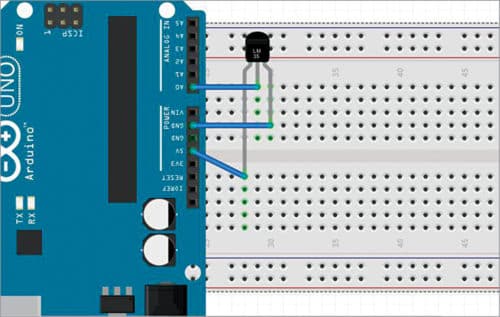
The circuit is built around Arduino Uno board and LM35 temperature sensor. Connect output pin (V0) of LM35 to A0 pin of Arduino board, Vcc pin to 5V pin of the board, and ground pin to common. Circuit connections of LM35 with Arduino Uno are shown in Fig. 1.
Arduino monitors the output pin of temperature sensor LM35 to calculate the ambient temperature. Then, it sends the value on the serial port to which it is connected. Processing software receives incoming data from the port and displays it on the graphical user interface (GUI). It also checks the temperature. If the temperature is below 40°C, green LED glows. If it is above 40°C, red LED glows and a pre-recorded voice alert is played on the laptop speaker.
The microcontroller (MCU) on Arduino has an inbuilt 10-bit analogue-to-digital converter (ADC). Using its ADC, Arduino monitors the output of LM35 through its analogue pin A0. Program (efy_temp.ino) in Arduino, as given below, performs multiplication and division using certain factors to give actual temperature.
temperature=(val×4.88)/10; //multiplication factor to convert the value into temperature
To understand the above relationship, note that ADC on Arduino gets 5V as a reference by default. So, to calculate step size, use the relationship given below.
Stepsize=Vref/2n
where n=number of bits
Here, we have a 10-bit ADC on Arduino. So,
Stepsize=5/1024=0.0048828= 4.88mV
Datasheet of LM35 says that, for every 1°C rise, there is an increase of 10mV in output.
Hence, temperature = (val×4.88mV)/10mV
Understanding the GUI
Processing IDE uses Cartesian coordinates (Fig. 2). It assumes the top-left corner of the rectangular GUI window as having (0,0) coordinates, and all other coordinates are taken with respect to it. To achieve the desired functionality, two libraries are used, namely, serial and minim.
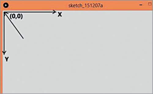
Minim library comes pre-installed with Processing IDE; it needs to be downloaded and installed as explained in the testing steps section.
Processing code (dee_efy.pde) is used to generate the GUI window. The code within setup() runs once and sets the size of the GUI window and loads the essential dependencies. The code inside draw loop runs repeatedly. serialEvent() function is called every time data comes on the serial port. Processing reads it as string and stores it in a variable named data.
Led() function takes care of the red and green LEDs based on the value of temperature.
The application can also be exported to run as a standalone app for Windows, Mac or Linux platforms by going to File>Export Application. Chose the platform for which you want to export and click OK.
Testing steps
- Download and install Arduino IDE from website and Processing software from this website.
- Connect Arduino board with laptop or computer using a USB cable and open Arduino code (efy_temp.ino) using Arduino IDE software. Under Tools, select the board as Arduino/Genuino Uno and correct COM port. Next, compile the code and upload it to Arduino board.
- Open Processing source code (dee_efy.pde) using Processing software. Add the audio library (minim) in this software for voice alerts. For this, go to Sketch>Import Library…>Add Library…>minim. In filter box, search for minim and click on Install, and wait for a few seconds.
- Add fonts for your GUI. For this, go to Tools>Create Font, select Arial-black-48 and click OK. Colour codes can be obtained from Tools>Color Selector option.
- Replace COM12 port number in the Processing code with your own COM port number. Check COM port under Windows Device Manager. Save the code before running it. Note that the pre-recorded audio files to be played, colour font file and Arduino code should be inside the data folder on your PC.
- Run the code and a GUI will open with temperature value, as shown in Fig. 3.
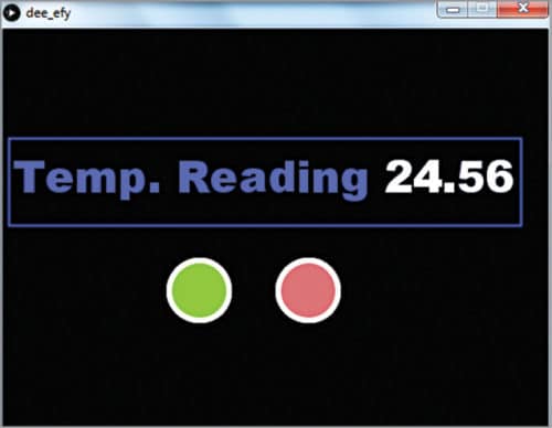
In the GUI, green LED will glow when temperature is below the pre-defined limit (40°C), and red LED will glow when temperature is above the pre-defined limit along with the voice alert.
Download Source Folder
Note
You can replace the voice alert’s audio (tempSafe.mp3 and tempWar.mp3) with any other alert audio you want, but make sure the format, that is, .mp3, is the same.
In case you want to change the temperature limit above which you want the alert, you can change it from if (convertedData>40) in Processing source code.
Deepankar Maithani is an electrical engineer and open source enthusiast. He specialises in the Internet of Things (IoT) technology and its security aspects.
This article was first published on 20 August 2019 and was updated on 20 February 2020.
Dear all thanks your source documents , I need more because by now I am working by this my project , so it is helpful please advice me and share with valuable comment.
sincerely yours
Kindly elaborate your query.