
An earlier design introduced a touch solid-state AC switch. The new version advances this concept with a sophisticated human radar sensing system that can also be configured for IoT and smart automation. The system uses 70% Indian components and is entirely Indian-engineered.
At its core lies a microwave doppler radar sensor that detects human motion with far greater reliability than traditional PIR or IR-based systems. Unlike PIR sensors that depend on heat signatures and often malfunction under sunlight, near heaters, or behind curtains, the microwave radar delivers superior penetration through non-metallic barriers, immunity to heat-induced false triggers, reduced sensitivity to small animals, and omnidirectional detection without requiring a direct line of sight.
POC Video Tutorial
Where most motion switches rely on PIR sensors and frequently cause false triggers, this radar-based system eliminates such issues. It also integrates an LDR to function only under low-light or nighttime conditions, making it ideal for automated lighting systems. Fig. 1 illustrates the prototype design.


The components for the system have been selected such that Indian substitutes are available wherever possible, enabling over 70 per cent localisation in the design. Table 1 lists the Bill of Materials, including part names, numbers, manufacturers, and Indian substitute options where applicable.
| Table 1: Bill Of Materials | |||||||
| Name | Designator | Footprint | QTY | Man. Part | Manufacturer | Indian Substitute Part No. | Indian Manufacturer |
| 100nF | C3 | C1206 | 1 | CC1206KKX7RYBB104 | YAGEO | 1206B104K251CT | Walsin |
| DB301V-3.5-2P-GN | CON1, CON2 | CONN-TH_DB301V-3.5-2P-GN | 2 | DB301V-3.5-2P-GN-S | DORABO | TL001R-3.5-2P | Connectwell |
| FPC Connector | FPC1 | OV2640 FPC 24P | 1 | AFC01-S24FCA-00 | JUSHUO | ZF5S-24-01-T-WT | Samtec Electronics India |
| VO2223A-X007T | IC1 | DIP-8_7P-L9.7-W6.4-P2.54-LS7.6-BL-PE7 | 1 | VO2223A-X007T | VISHAY | VO2223A-X007T | VISHAY |
| 120Ω | R1 | R0603 | 1 | 0603WAF1200T5E | UNI-ROYAL | CRCW0603120RFKEA | VISHAY |
| 100Ω | R3 | RES-SMD_L6.4-W3.2-R2512 | 1 | SR2512FK-7W100RL | YAGEO | 100Ω SMD resistor | HTR-INDIA, Watts Electronics, Kusum/KOHM |
| RCWL 0516 | U1 | RCWL-0516 | 1 | RCWL-0516 | NA | NA | |
| LDR | U2 | UNIVIBE LAMP-LDR ARRANGEMENT_LDR3 | 1 | NA | NA | ||
| LD05-23B05R2_C42432360 | U4 | PWRM-TH_LD05-23BXXR2 | 1 | LD05-23B05R2 | LZTEC | RECOM RAC05-05SK | RECOM Power India Pvt Ltd |
| IoT Board | MOD1 | NA | ESP S3, Arduino IoT Kit | IndusBoard Coin V2 | IndusBoard V2 | ||
Human Radar Motion Switch – Connections and Modes
In this upgraded version, the separate optocoupler and triac ICs have been replaced with a single integrated optotriac that combines both functions. This component, sourced from an Indian manufacturer, can directly drive AC loads up to 1A RMS across the 110-230V range, as specified in the VO2223A datasheet.
This capability enables automatic control of standard LED and CFL bulbs used in residential and commercial environments. An FPC connector allows interfacing with development boards, including the IndusBoard Coin, extending functionality for IoT-based human radar sensing or solid-state relay applications.
This single compact design supports multiple modes of operation, allowing configuration for standalone use or full IoT integration.
The RCWL microwave Doppler radar detects human presence using the Doppler effect. An optional LDR input allows night-only operation, keeping lights off during the day and automatically activating them at night when motion is detected.
According to the optotriac datasheet (refer Fig. 2), the triac can directly drive an AC bulb via pins 8 and 6. A snubber circuit may be added for inductive loads. Fig. 2 presents the VO2223A configuration circuit.

The design includes an FPC connector for IoT board integration and can be configured in four modes: Mode 1, Mode 2, Mode 3, and Mode 4.
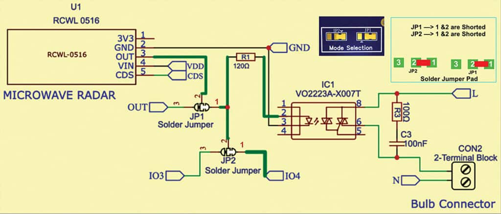
Mode 1: Human radar SSR mode
In this mode, the three-point solder jumper JP1 is shorted to trigger the optotriac based on human motion detected by the sensor. In this mode JP1=1 and 2 shorted and JP2=1 and 2 shorted.
In this standalone configuration, the circuit functions as a fully automatic motion-activated light switch. The RCWL-0516 radar sensor detects human motion using the Doppler effect, producing a high output at the OUT pin for about three seconds upon detection. This signal is routed directly to the optotriac (VO2223A-X007T) through solder jumper JP1, which shorts pins 1 and 3. As shown in Fig. 3, the green line runs from the radar OUT to JP1, then to R1=120Ω and optotriac pin 1. The optotriac’s internal triac (pins 4-6) then drives the AC load, such as an LED or CFL bulb up to 1A RMS, via connector CON2.
A snubber network (R3=100Ω and C3=100nF across pins 4-6) ensures stable operation, particularly for resistive loads. The CDS pin can be left open or connected to an LDR through a 10kΩ divider for night-only operation. No FPC connection is required in this mode, making it suitable for basic home lighting automation. When JP1 is shorted, the circuit acts as a standalone motion-activated light switch. The radar sensor output drives the optotriac directly, turning on the connected bulb whenever motion is detected.
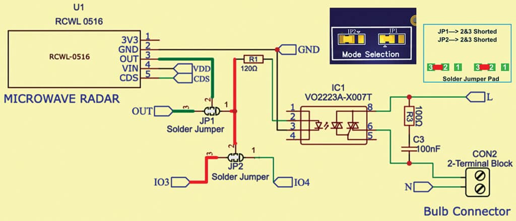
Mode 2: Human radar sensor mode
In this mode, the board functions as a dedicated motion sensor and alert unit, bypassing the SSR section for external control through the FPC connector. The solder jumper SJ1 (pin 1 bridged to the OUT pin, as shown in Fig. 4) routes the radar’s OUT signal directly to FPC pin 1, while JP1 remains open. This allows the human motion signal from the RCWL-0516 sensor to be sent to an external controller, such as the IndusBoard Coin, for processing or triggering alerts. In this mode, JP1=2 and 3 shorted and JP2=2 and 3 shorted.
To activate the SSR externally, connect the MCU I/O pin (for example, pin 3 from the IndusBoard) to the optotriac trigger input. In this configuration, the radar sensor output is sent to an external controller via the FPC connector for motion-based alerts or control, with the SSR bypassed.
Mode 3: IoT SSR (solid-state relay) mode
In this mode, the board operates as a remotely controllable solid-state relay, bypassing the radar sensor for direct IoT-based control. The solder jumper JP2 is shorted across pins 1-2 (as shown in Fig. 5) to enable triggering of the optotriac through the IndusBoard’s I/O pin 4 via the FPC connector. The IndusBoard sends control signals wirelessly, for example, through an MQTT app or IoT dashboard, to switch the connected AC load (for example, a bulb) on or off. In this mode JP2=2 and 3 shorted.
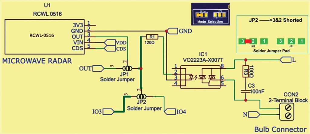

A built-in snubber network ensures clean and stable AC switching. JP2 shorted across pins 1 and 2 enables remote operation of the SSR via IndusBoard signals, allowing IoT-based control of the connected load.
Mode 4: Human radar IoT SSR +sensor mode
In this hybrid mode, the circuit combines both automatic motion-based control and IoT-based monitoring for advanced automation. Human motion triggers local SSR switching while simultaneously sending status updates to the IndusBoard through the FPC connector, providing both sensor and light-state feedback. All jumpers shorted.
Configure JP1 shorted (radar OUT to optotriac input) and SJ1 bridged (OUT to IO3 for sensor feedback). JP2 may also be shorted if remote control via IO4 is required. The radar’s OUT signal is routed in two ways: locally to the optotriac for immediate switching, and to the IndusBoard’s FPC pin IO3 for alerts such as ‘motion detected’ notifications. The light (opto) state can be mirrored back via IO4 for real-time IoT dashboard updates.
An optional LDR can be connected to the CDS pin for night-only activation.
Refer to Fig. 2 for the dual-path configuration (JP1 and SJ1 shorted) and Fig. 3 for FPC pin assignments (pins 3-4 active, VDD/GND on pins 25-26 for 3.3V/5V compatibility).
Mode 4 integrates radar sensing with IoT control. The radar output drives the local SSR and simultaneously communicates motion and light states to the IndusBoard for monitoring or remote control.
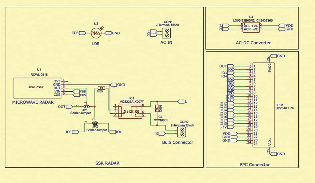
The four modes above represent different functional settings. Fig. 7 shows the final circuit of the motion sensor system. For powering the radar sensor, IndusBoard, and opto-isolator, a DC supply is derived through an AC-DC converter mounted on the PCB. The AC input is connected to the screw terminal CON1, while the load, such as a bulb or low-power fan, is connected to CON2.
PCB Design
The final system’s PCB design has been kept as compact as possible by using a multilayer layout and SMT components. The top layer includes the radar module, optotriac, and other discrete components, while the bottom layer houses the AC-DC power converter and connectors.
The compact multilayer PCB layout separates AC and DC sections to ensure safety and minimise interference, with SMT components used for space efficiency.
Testing Human Radar Motion Switch
For testing, first assemble all the components on the PCB as shown in Fig. 1. Connect the AC power line to the screw terminal CON1 and the load, such as a bulb, to CON2. Based on the solder jumper configuration, if set to a particular mode, the system automatically turns the light on or off according to motion detection. When an LDR is added to the radar sensor module, the circuit operates according to motion only during low-light or night conditions. The same principle applies to the other mode configurations.
For IoT functionality, connect the IndusBoard Coin using the FPC connector.
The IoT code and app development for this system will be covered in a subsequent article to be published soon.
Ashwini Kumar Sinha, an IoT and AI enthusiast, is a Tech Journalist at EFY.