


 In our usual busy routine, one of the reasons for people hesitating to keep plants at their home is that people forget to water them every day. To solve this issue here is a circuit that is useful for watering plants automatically without any human effort. This circuit automatically waters the plants every day in the morning for the watering duration that the user has set. Want one? You can build one for yourself in just a few hours.
Circuit and Working
The Circuit diagram of the Automatic Plant Watering System with Melody is shown in fig.1. In this circuit, LDR detects light and pour water in the morning. It is built around NE555 (IC1 and IC3), UDN2981 (IC2) Source driver, UM66 (IC4) Simple melody generator, Voltage Regulator 7809 (IC5), BC547 Transistor (T1), a Light Dependent Resistor (LDR1) and a few other components.
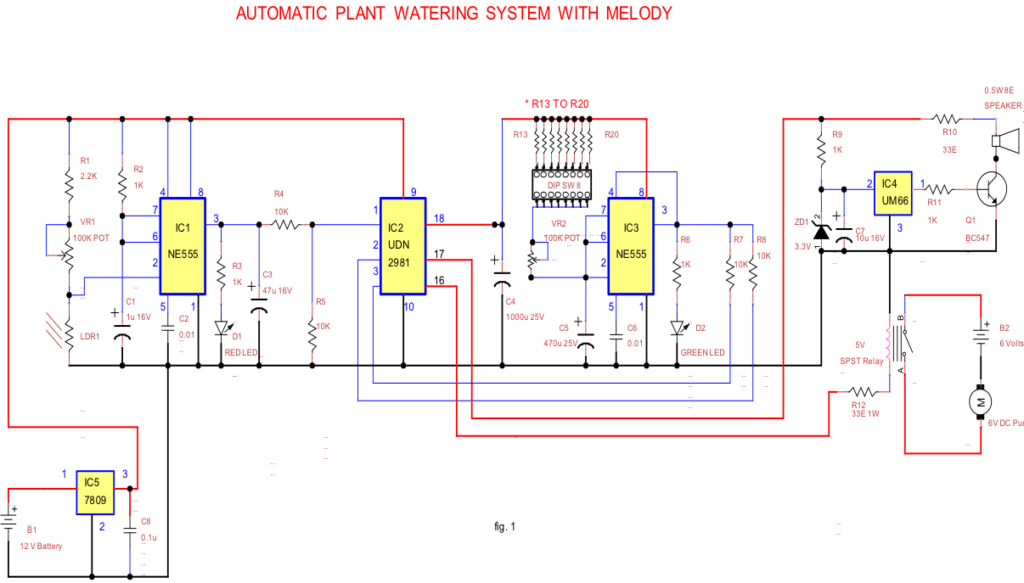
IC1 configured as monostable. The 555 timer acts as a “one-shot” pulse generator. The pulse begins at the output pin 3 when the 555 timer receives a signal at the trigger input pin 2 and that falls below a 1/3 of the voltage supply. The width of the output pulse is determined by the time constant of an R2 and C1. The output pulse ends when the voltage on the capacitor equals 2/3 of the supply voltage. This is determined by the relationship T = 1.1R*C.

UDN2981 (IC2) Source driver. This 8-channel source driver is useful for interfacing between low-level logic and high-current loads. Its maximum output current is 500mA. UM66 (IC4) is a melody generator IC. 7809 (IC5) is a voltage regulator, it regulates 12volt to steady 9volt.
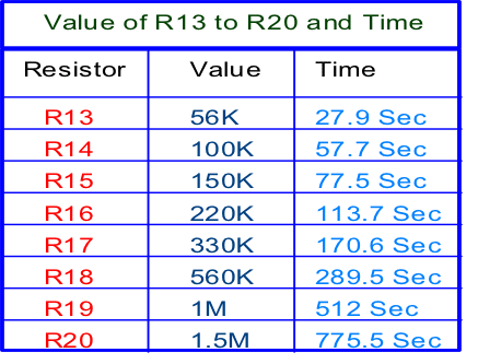
The LDR is paired with a potential divider to feed the trigger voltage to the NE555 (IC1). When light falls on the LDR, its resistance and the potential difference between pin 2 of IC1 & ground get decreased. In this condition, the output pin 3 of IC1 remains high and it causes RED LED D1 to ON. The sensitivity of LDR can be adjusted by using a VR1 variable resistor. When UDN2981 (IC2) input pin 1 becomes high, its output pin 18 and NE555 (IC3) pin 8 also becomes high. This leads to the pin no 2 of IC3 gets grounded through capacitor C5 and pin no 3 to go high. This causes GREEN LED D2 to ON and makes reset pin 4 to go high for a certain period of time which is determined by the value of C5 and R13 to R20. When the capacitor C5 charges to 2/3 of the supply voltage, the output of (IC3) goes low, grounding the reset pin 4 and thus output pin 3 becomes low. DIP Switch is used for different time setting.
When the IC3 output pin is high, IC2 UDN 2981 input pins 2 and 3 become high through R7 and R8 and this causes IC2 output pin 16 and 17 to become high. When output pin 16 of IC2 becomes high relay is picked up through R14. Hence 6Volts DC pump starts working and as a result, watering happens. UM66 (IC4) is a melody generator IC. Its maximum working voltage is 3.3V. A Zener diode is used to provide the maximum required voltage. Melody IC UM66 gets the input from UDN 2981 and its output is fed to the base of transistor T1 through R11.R10 is used to set the threshold operation of the circuit.7809 IC5 is a fixed linear voltage regulator and this IC maintains constant 9 Volts supply to the circuit. Instead of 6Volts DC pump, appropriate rated Solenoid valve or pumps can be used.
Construction and Testing
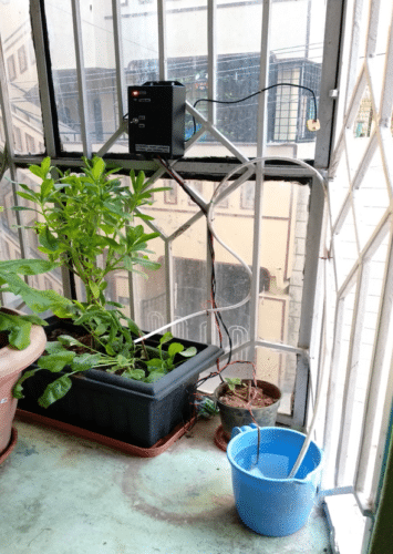
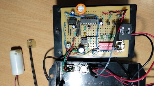
Assemble the circuit on a common PCB and enclose it in a suitable box. Connect the Batteries B1 and B2. Affix LDR at a suitable location such that sunlight falls on it directly. Adjust the VR1 for appropriate output. Select the DIP switch in appropriate position for the desired watering duration. Adjust VR2 for fine time adjustment. This circuit consumes 10 to 20 mA current in the night, 20 to 35mA in a day and 150 to 200 mA during watering. So rechargeable batteries are preferred for smooth working. Proposed Prototype and enclosure is shown in fig.2 and fig.3.
Download Source Folder
DOES IT REALLY WORKS???
Hi Anushya, this is a prototype circuit submitted by one of our guest users and is not verified by us.
What is the use of UDN2981 here? Explain the working of the prototype in detailed
send me videos on this
where is the table of components
Plz send the pcb layout of this circuit
Where is the components for above project
You can get components list here