This reaction time game tests the time taken by two players to react, and declare the fastest one as a winner. To do this I am using external interrupts and pin change interrupts in atmega328p. It gives four chance to each play, time of each chance is summed up and then the player with minimum time is declared as the winner.
For the demo purpose, I’ll be using pseudo random function in it, just to keep track.
This game has precision of 1ms and accuracy of about +/- 4ms.
It also displays the concept of debouncing.

This game’s main motive is to show the beauty of external interrupts over polling and to show the how to reduce debouncing effect using software modifications.
Components
1) Arduino with Atmega328p
2) Jumper wires
3) Bread Board
4) Push Buttons
5) 1k Resistors
6) LEDs
Background
My project is inspired from fastest finger first game, in which there are two players, and both get four chances and reaction time of all four chances are summed up, whoever has the minimum reaction time wins the game.
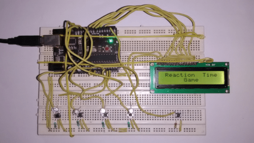
- Game starts with the display on LCD which reads “Reaction Time Game” and then “Push Button to Start”.
- When the push button is pressed, game starts in 3.5secs.
- Then one out of four LED glows Player1 is expected to press corresponding button to that LED, time is recorded for the same, if Player1 presses another button that does not correspond to that specific LED than a penalty of 1000ms is imposed along with the recorded time.
- Score after each turn is displayed on LCD and this thing is repeated for four times.
- After that Player2 begins and same thing is repeated.
- Then score of both the players are compared and fastest one is declared winner.
- After around two seconds “Push Button to Play Again” is displayed on LCD.
Construction
Uploading code to arduino
f = <source_code’s_file_name>
h = avr-gcc -g -mmcu=atmega328p -Wall -Os $(h).c $(f).c -o $(f).elf
avr-objcopy -j .text -j .data -O ihex $(f).elf $(f).hex
sudo avrdude -F -V -c arduino -p m328p -P /dev/ttyUSB* -b 57600 -e -U flash:w:$(f).hex
Just type these four commands, in the same order, in your terminal and remember to put the source code’s filename in variable “f” and header filename in variable “h”. These commands are for Linux users only.
First command stores the filename in variable “f”, second command is used to convert source code to the .elf file, third command is used to convert that .elf file to .hex file which can be uploaded on atmega328p, fourth command is used to upload that .hex file.
All source code files and libraries along with headers are there in codes.zip. Place all of them in same directory and run the above commands.
External Interrupts
External interrupts are very useful to interact with physical world, because of its unpredictable nature.
There are two ways of sensing data from different pins, one is polling other is using interrupts. Both polling and interrupts have pros and cons associated with them.
In polling you check status of each pin in a sequential manner:
pros:
1) Everyone gets a fair chance
cons:
1) Inefficient, can’t do some other activity in between, specially must go and check
2) Loss of data might occur in an unpredictable scenario.
Whereas, in interrupts you let your microcontroller do some other important stuff and whenever an interrupt is generated you stop the normal working of microcontroller and change its behavior accordingly.
pros:
1) Efficient, can do some other work in between
2) No loss of data
cons:
1) Extra resources on hardware level are required
Registers used
| EICRA | ||||||||
| Bit | 0 | 1 | 2 | 3 | 4 | 5 | 6 | 7 |
| 0x7A | ISC00 | ISC01 | ISC10 | ISC11 | – | – | – | – |
| Initial Value | 0 | 0 | 0 | 0 | 0 | 0 | 0 | 0 |
- Bit 7..4 – Res: Reserved Bits
These bits are unused bits in the ATmega48PA/88PA/168PA/328P, and will always read as zero. - Bit 3, 2 – ISC11, ISC10: Interrupt Sense Control 1 Bit 1 and Bit 0
Used for Interrupt 1 Sense Control, check the table below - Bit 1, 0 – ISC01, ISC00: Interrupt Sense Control 0 Bit 1 and Bit 0
Used for Interrupt 0 Sense Control, check the table below
| EIMSK | ||||||||
| Bit | 0 | 1 | 2 | 3 | 4 | 5 | 6 | 7 |
| 0x7A | INT0 | INT1 | – | – | – | – | – | – |
| Initial Value | 0 | 0 | 0 | 0 | 0 | 0 | 0 | 0 |
- Bit 7:2 – Reserved
These bits are unused bits in the ATmega48A/PA/88A/PA/168A/PA/328/P, and will always read as zero. - Bit 1 – INT1: External Interrupt Request 1 Enable
When the INT1 bit is set (one) and the I-bit in the Status Register (SREG) is set (one), the external pin interrupt is enabled. - Bit 0 – INT0: External Interrupt Request 0 Enable
When the INT0 bit is set (one) and the I-bit in the Status Register (SREG) is set (one), the external pin interrupt is enabled.
| PCICR | ||||||||
| Bit | 0 | 1 | 2 | 3 | 4 | 5 | 6 | 7 |
| 0x7A | PCIE0 | PCIE1 | PCIE2 | – | – | – | – | – |
| Initial Value | 0 | 0 | 0 | 0 | 0 | 0 | 0 | 0 |
- Bit 7:3 – Reserved
These bits are unused bits in the ATmega48A/PA/88A/PA/168A/PA/328/P, and will always read as zero. - Bit 2 – PCIE2: Pin Change Interrupt Enable 2
When the PCIE2 bit is set (one) and the I-bit in the Status Register (SREG) is set (one), pin change interrupt 2 is enabled. Any change on any enabled PCINT[23:16] pin will cause an interrupt. - Bit 1 – PCIE1: Pin Change Interrupt Enable 1
When the PCIE1 bit is set (one) and the I-bit in the Status Register (SREG) is set (one), pin change interrupt 1 is enabled. Any change on any enabled PCINT[14:8] pin will cause an interrupt. - Bit 0 – PCIE0: Pin Change Interrupt Enable 0
When the PCIE0 bit is set (one) and the I-bit in the Status Register (SREG) is set (one), pin change interrupt 0 is enabled. Any change on any enabled PCINT[7:0] pin will cause an interrupt.
| PCMSK1 | ||||||||
| Bit | 0 | 1 | 2 | 3 | 4 | 5 | 6 | 7 |
| 0x7A | PCINT8 | PCINT9 | PCINT10 | PCINT11 | PCINT12 | PCINT13 | – | – |
| Initial Value | 0 | 0 | 0 | 0 | 0 | 0 | 0 | 0 |
- Bit 7 – Reserved
This bit is an unused bit in the ATmega48A/PA/88A/PA/168A/PA/328/P, and will always read as zero. - Bit 6:0 – PCINT[14:8]: Pin Change Enable Mask 14…8
Each PCINT[14:8]-bit selects whether pin change interrupt is enabled on the corresponding I/O pin. If PCINT[14:8] is set and the PCIE1 bit in PCICR is set, pin change interrupt is enabled on the corresponding I/O pin. If PCINT[14:8] is cleared, pin change interrupt on the corresponding I/O pin is disabled.
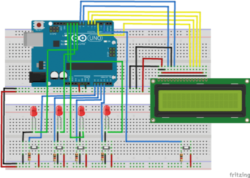
Reaction time game circuit