


 Here is a simple circuit using different colour LEDs that makes your clock glow in different colours of rainbow. The clock’s dial (shown in Fig. 2) is lit by colour LEDs around it that glow one by one.
The circuit is built around popular timer NE555 (IC1), decade counter CD4017 (IC2) and some discrete components. The clock pulse output of the astable multivibrator built around IC1 is fed to decade counter IC2. The outputs of the decade counter are fed to the bases of transistors T1 through T6 to drive the LEDs (LED1 through LED24).
A high at any of the outputs (Q0 through Q5) of IC2 will drive the corresponding colour LEDs. As the input clock changes, different colour LEDs glow, thus illuminating the dial in different colours.

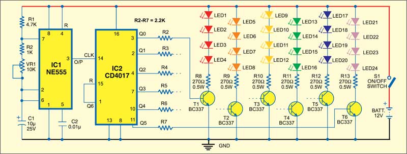
Since the LEDs are current-operated devices, the current through the LEDs is limited to a safe value by using resistors R8 through R13.
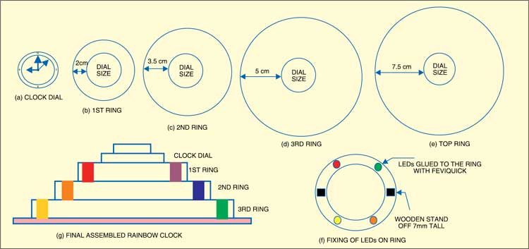
The circuit is relatively simple to assemble but construction of the cabinet requires accuracy and patience. As shown in the diagram, use a 4-6mm HD plastic sheet or plywood. Get the broad rings cut at a local saw mill. The diameter of the internal hole of each ring is the same and matches the diameter of the clock dial. The outer diameter of each successive ring increases by 1.5 cm, so LEDs remains invisible. Stand-offs are cut from wooden battens used in electrical wiring and fixed with Fevibond.
The circuit works off a 12V battery. Alternatively, a 12V, 500mA adaptor can be used.
When LEDs and stand-offs are glued to the rings using adhesive, allow the adhesive to dry for three to four hours. Ring-1 has LEDs from outputs Q0 and Q5. Ring-2 has LEDs from outputs Q1 and Q4. Ring-3 has LEDs from outputs Q2 and Q3. Selecting LEDs’ colour for each output is an individual’s choice.
Purchase a white-dial clock with embossed black numerals. Because of the gap between successive rings, a nice glow of LED light will be visible around the clock.
Assemble the circuit on a general-purpose PCB and enclose in a suitable circular cabinet. Extend the different LEDs through wires and fix them on the respective rings as shown in Fig. 2.
