


Controlling two strong wheel motors with one controller is tricky. This design shows how you can handle motor control, sensing, and protection all in one system.
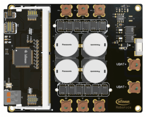
Design engineers building autonomous mobile robots often struggle with controlling two high-power brushless DC (BLDC) wheel motors using limited processing resources, while still keeping the system safe, efficient, and easy to integrate. The REF_48V_2X1KW_ASFOC reference design from Infineon solves this by showing how one microcontroller (MCU) can run field-oriented control (FOC) for two 1 kW synchronous BLDC motors and still handle sensing, protection, and communication in real time.
The design addresses the practical issue of reliable motor control in robots where commands come over the controller area network (CAN) bus or through the serial wire debug (SWD) interface. The MCU reads motor position and speed from the magnetic angle sensor, feeds the data into the FOC loop, and then produces the switching pattern needed to run each motor through six pulse-width modulation (PWM) outputs. This reduces the burden of coordinating multiple controllers while keeping the drive train predictable.

You might also face the challenge of driving high-current metal-oxide semiconductor field-effect transistor (MOSFET) stages from low-current PWM outputs. The gate drivers in this design solve that gap by amplifying the signals to control the OptiMOS 6 MOSFETs in each inverter phase. With a 48 V bus and loads up to 1 kW per motor, the design shows how to handle continuous currents up to 20 A without compromising stability.
Accurate current feedback is another common pain point. Each low-side MOSFET uses a shunt resistor, but its small voltage must be conditioned before the analog-to-digital converter (ADC) reads it. A dedicated current-sense operational amplifier (op amp) handles the offsetting and gain, making the feedback loop more dependable and removing guesswork for engineers building their own sensing stage.

System protection is a recurring concern in robotics, especially when motors or power converters must disconnect during faults. The design includes two power management integrated circuits (PMICs) that provide overcurrent protection, overvoltage protection, and in-line current sensing. A high-side disconnect switch paired with two LinearFETs gives engineers a ready solution for safe power cutoff during abnormal conditions.
Current measurement on the main rail is handled through a magnetic current sensor that solves the problem of stray magnetic fields often seen in compact robots. A coreless structure and differential Hall probes cancel ambient fields and extract only the real current signal. A built-in high-performance amplifier processes the magnetic data, applies temperature and stress compensation, and drives a clean analog output for the MCU.
The design reinforces two guiding principles for robot drive train development: understand the final purpose early and prepare for the toughest operating conditions. By planning for inclines, traction loss, and heavy loads, engineers can use this reference design as a starting point that already anticipates many of these real-world stresses.
Infineon has tested this reference design. It comes with a bill of materials (BOM), schematics, assembly drawing, printed circuit board (PCB) layout, and more. The company’s website has additional data about the reference design. To read more about this reference design, click here.
