
The refrigerator is one of the most heavily used household appliances, operating continuously throughout the year. Therefore, any improvement in its operating conditions can enhance food cooling performance. Reduced load on the compressor also helps extend its service life, while delivering modest power savings.
POC Video Tutorial:
Refrigerators remove heat from stored food and dissipate it through the condenser coils. In older models, these coils were mounted on the rear side, where the exposed black coils released heat directly into the surrounding air. In newer versions, the condenser coils are embedded inside both side walls of the refrigerator enclosure. Touching the side walls often reveals warm areas, indicating the location of the coils within the enclosure. Heat from the condenser coils is transferred to these walls, which then radiate it to the outside environment. The wall temperature typically rises to about 10°C above ambient.
A clearance of 5cm to 10cm is recommended on both sides of the refrigerator to allow proper air circulation. However, this clearance is often inadequate due to space constraints. In many cases, the available gap is also used to store household items, which further obstructs airflow. As a result, the refrigerator remains surrounded by warm air, reducing its cooling efficiency.

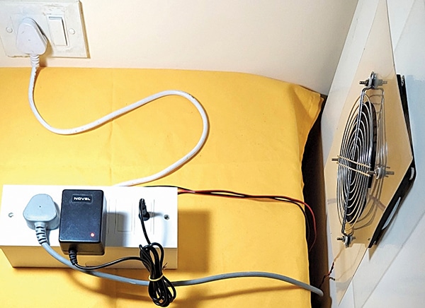
A simple fan-cooling system addresses this issue. The cooling fans can be magnetically attached to both sides of the fridge using small magnets. The fans switch on automatically whenever the compressor cycle starts. This is achieved by sensing the compressor current using a current transformer (CT). When the CT detects current flow, the fans turn on, and they switch off automatically when the compressor cycle ends.
Compressor current sensing
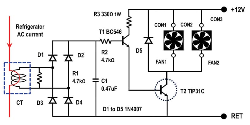
The circuit diagram of the proposed system is shown in Fig. 1. It consists of a CT having a ratio of 5A to 5mA output at the secondary. Typically, a compressor draws a few hundred milliamperes. Resistor R1 (4.7kΩ) acts as a burden on the CT. Caution: Do not disconnect the burden resistor from the CT terminals. Without the burden resistor, the CT will generate a high voltage and the coil may burn out.

CT details
1. Compressor current (measured): 500mA (rms)
2. Number of primary turns: 2
3. Current in the secondary: 1mA
4. Voltage across burden R1: 4.7V (rms)
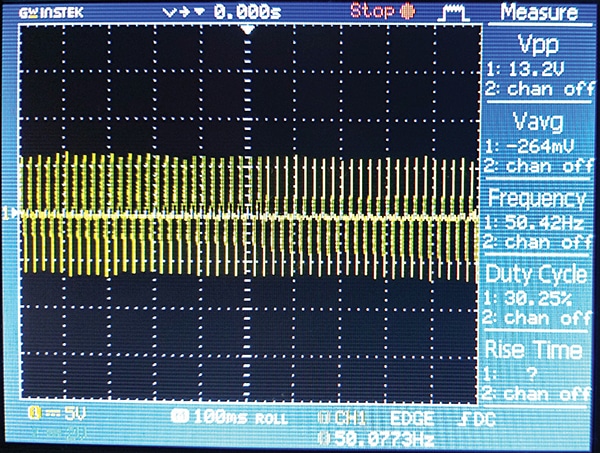
5. Peak to peak voltage across R1: 2√2×4.7=13.3Vpp
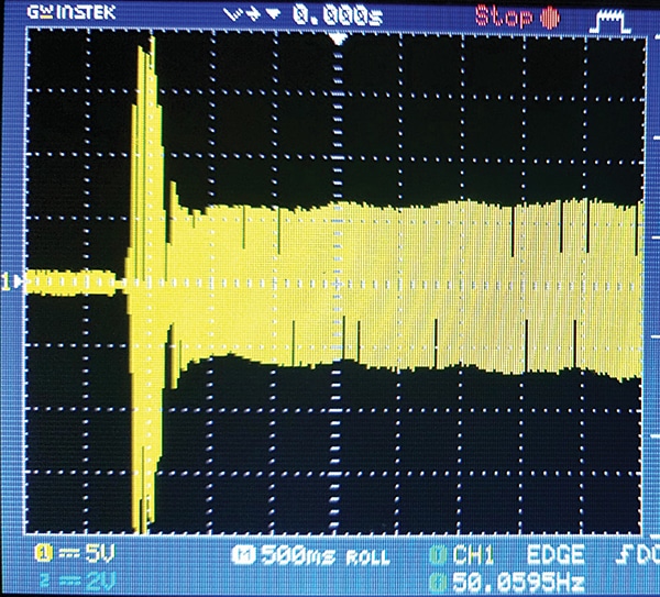
Fig. 2 shows the starting current waveform of the compressor (CT burden 4.7kΩ, primary 2 turns), while Fig. 3 shows the running current waveform. The CT output is rectified using a full-wave rectifier consisting of diodes D1 through D4 (1N4007). The rectified voltage is filtered using C1 (0.47µF) box capacitor. This rectified current signal drives transistor T1 (BC546) through resistor R2 (4.7kΩ). T1 drives the power transistor T2 (TIP31C) using current-limiting resistor R3 (330Ω, 1W). T2 is mounted on a small heat-sink. In the collector circuit of T2, two 12V instrument cooling fans are connected. D5 (1N4007) acts as a free-wheeling diode and eliminates voltage overshoot whenever the fans turn off.
| Parts List |
| Semiconductors: T1 – BC546 NPN transistor T2 – TIP31C NPN power transistor (TO220 package) D1-D5 – 1N4007 rectifier diode Resistors (all 1/4-watt, ±5% carbon): R1, R2 – 4.7 kilo-ohm R3 – 330-ohm, 1-watt Capacitor: C1 – 0.47µF 100V box type Miscellaneous: FAN1, FAN2 – 12V DC 0.25A, BLDC cooling fan 120mm×120mm CT – Current transformer with ratio of 5A:5mA CON1, CON2 – Connector 2-pin polarised CON3 – 2-pin solderable terminals Heat sink – For TO220 package Magnets – Ring magnets 12mm OD, 4mm ID, 4mm thickness (4) Finger guards – For 120mm fans (2) Adaptor – 12V DC, 1A DC Jack – 12V DC socket for adaptor AC sockets – 3-pin 5A AC socket (2) Plastic film – A4 size plastic film (stiff) Switch box – For mounting 2 sockets |
Construction
The assembled prototype of the system is shown in Fig. 4. Polarised 2-pin connectors CON1 and CON2 are used to connect the fans. CON3 (terminal block) is used to connect the +12V and RET wires coming from the DC jack. An adaptor (12V, 1A) is used to power the circuit.
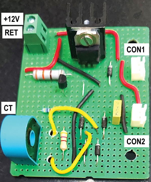
The PCB layout is shown in Fig. 4. This PCB is mounted inside a switch box using the two mounting holes.
Fan assembly
Low-noise cooling fans are selected. A larger 120mm×120mm fan helps reduce noise while providing a bigger cooling area.
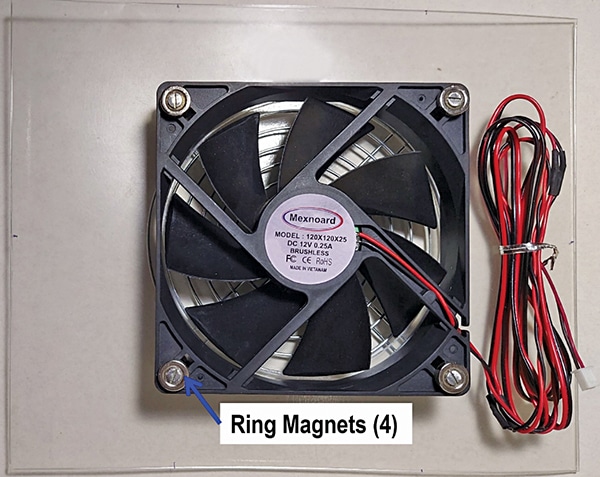
Fig. 5 shows the front view of the fan assembly. Four ring magnets (12mm dia×4mm thick) are fixed at the four mounting holes of the fan using M3×40mm screws. A close-up view of the magnets is shown in Fig. 6.
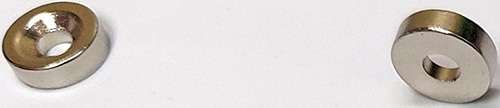
The screws are passed through the holes of the magnet and fixed as shown. The magnets create a 4mm gap between the the fridge surface and the fan blades. If more gap is required for smoother airflow, extra nylon washers can be added between the magnet and the fan housing.
This assembly can be magnetically attached at any desired location on the fridge side walls. Do not drag the fan on the fridge surface, as it may scratch the paint.
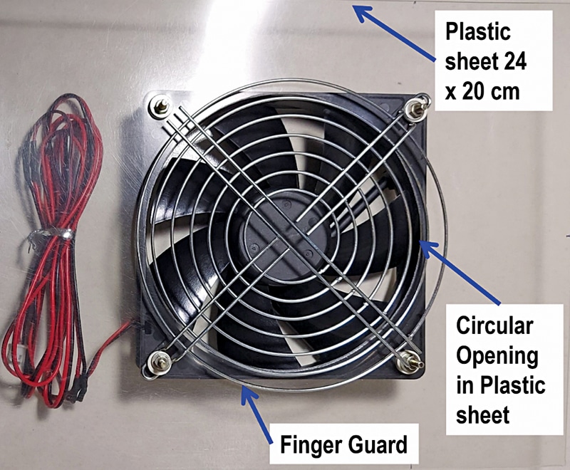
Fig. 7 shows the back-side view. A stiff plastic sheet of about 240mm×200mm is fixed as shown. A circular opening of the same size as the fan blade diameter is cut in the plastic sheet to allow airflow.
A finger guard is then placed, and the nuts are tightened. The plastic sheet redirects airflow from the fan onto the fridge surface, thus increasing the effective cooling area.
Fan power consumption
- Fan operating voltage: 12V DC
- Fan operating current: 125mA (measured)
- Power consumed: 12×0.125= 1.5W
- No of fans: 2
- Total power consumed: 2×1.5 =3W
- Compressor duty cycle: 50%
- Energy consumed in 24 hrs: 24×0.5×3=36Wh
- Energy consumed/month: 36×30=1080Wh (about one unit)
- Running cost/month: ₹5
Wiring and assembly
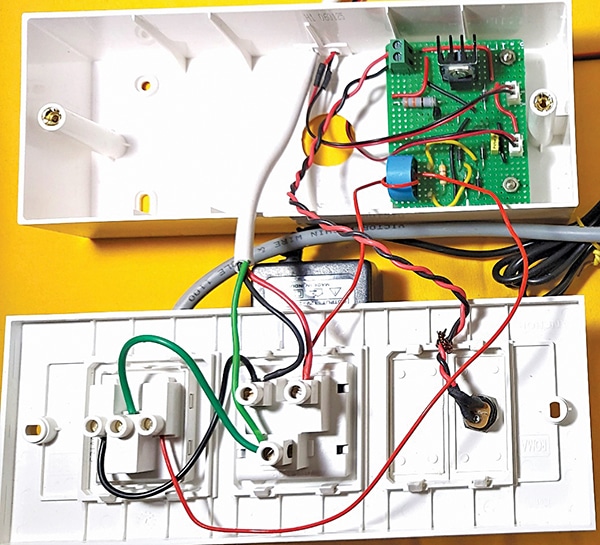
Fig. 8 shows the wiring diagram. Two 5A sockets are used here, one to power the adaptor and the other to power the fridge.
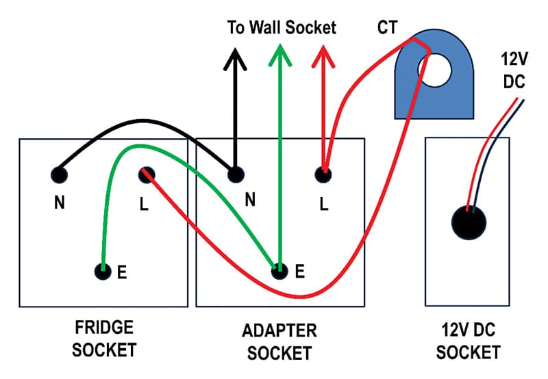
A short cable with a 3-pin plug is used to get power from the wall outlet where the refrigerator is currently plugged in. The phase wire is first passed through the CT and then connected to the socket meant for the fridge. The actual wiring is shown in Fig. 9.
Caution
Both 230V and 12V supplies are present in the same enclosure. Therefore, extra care must be taken while wiring.
Use good-quality sockets in which the terminals are not exposed. It is recommended to cover the sockets with a plastic sheet so that the PCB is completely isolated from 230V.
Results
The proposed system was tested on a refrigerator under real-life working conditions. The wall temperature profiles for fan-on and fan-off conditions were measured.
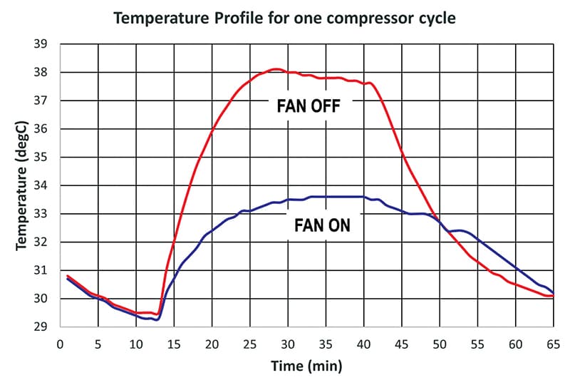
From the graphs shown in Fig. 11, it is observed that the peak temperature is almost 5°C lower when the fan is running. This reduction in fridge wall temperature provides following benefits:
- Improved cooling efficiency, less food spoilage
- Less load on the compressor, hence longer life
- The user may be able to reduce the internal fridge temperature setting by one or two steps while maintaining the same cooling performance
- Moderate power savings and a small reduction in the electricity bill
A small reduction in power consumption may save 25 to 50 rupees on the monthly bill. The actual savings will depend upon the following factors:
- Refrigerator capacity in litres
- Star rating (the lower the star rating, the higher the the savings)
- Free space around the fridge walls. If the gap is very small, forced cooling will provide better savings
- Savings are likely to be higher in the summer
- Heavy usage results in frequent fridge-door opening
Tips for further improvement
- Instead of a fan with a plastic housing, select one with aluminium housing. The aluminium housing will absorb heat from the fridge walls, which will then be removed by the fan airflow.
- It is also observed that when the compressor and fans turn off, some heat remains stored in the walls. It takes a few more minutes to dissipate this stored heat. If the fan turn-off is delayed by a few minutes after the compressor has stopped, this heat can be dissipated faster.
- For large-capacity refrigerators, four fans are recommended.
The proposed fan-cooling system is very easy to install. It improves the overall cooling performance of the refrigerator and offers moderate savings in the the electricity bill.
OEM refrigerator manufacturers can include this as an optional feature. In that case, the system cost will come down significantly, and even the CT will not be required.
The user can opt for this feature at the time of purchase by paying a small extra amount. For powering the fans, connectors could be provided on the back wall of the fridge. The user can then easily plug in or remove the fans as desired.
Dr Vijay Deshpande currently works for solar energy projects. He has worked as electronics hardware engineer in several companies