
In today’s fast-paced life, we often leave our mobile chargers, Laptop chargers or small appliances plugged in longer than necessary, especially during sleeping. This not only wastes electricity but can also reduce battery life and pose safety risks. Also, many times, we forget to switch off the pump for which the overhead tank overflows, causing wastage of water & energy. To solve such a problem, here’s a simple and cost-effective DIY Smart Power Cut-Off Timer switch that automatically switches OFF power to a connected device after a preset time. This cut-off timer device has the following benefits:
- Automatic power cut-off after preset time (time selection range: 0.1sec-999 minutes)
- Prevents overcharging of Mobile phones, laptops, etc.
- Prevents safety hazards due to overcharging of the Li-ion battery
- Prevents overflow of the water pump
- Saves electricity
- Simple and low-cost design
- Compact and portable
Automatic Power Cut-Off Timer Features
This project uses a readily available, versatile digital timer module, HCW-M421 and can be built inside a compact enclosure, making it ideal for everyday use. This versatile timer module has many modes using its various built-in programs, but for our power cut-off timer module, we will use only one mode (program P1.2). In this mode, the timer will actuate the relay, count down the preset time, which will be displayed in the built-in 3-digit seven-segment display and after the countdown is over, it will switch off the relay. If we press the reset button before completion of the countdown, the timer will start from the initial stage.
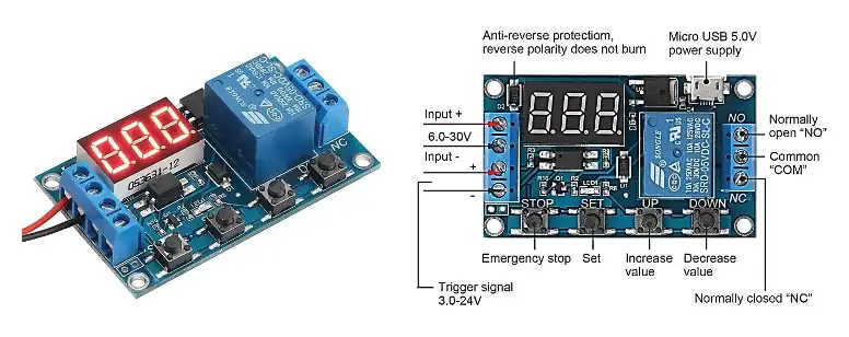
The timer module works on a wide range of DC voltages from 6V to 30V. For triggering the timer or starting the countdown, either a separate signal voltage of 3v to 24v DC can be used or directly positive terminal of the supply voltage can be connected to the trigger point momentarily. Here, a push-to-on switch has been used to connect the supply voltage to the trigger point. The timer can also operate through a mobile charger with a micro USB terminal, which has not been used in this gadget. At the output, there are three points of an in-built 5V relay. We have used Common and NO point to switch of the plug socket where a mobile or laptop charger or pump or a desired device will be connected, which we want to control through this cut-off timer.
The timer module has 4 control switches with the following actions:
STOP (EMERGENCY STOP) BUTTON: This button is used to switch off the load at any point off time, though the counting down operation of the timer continues.
SET BUTTON: This button is used to set the mode of Timer selecting the particular program (out of programs P1.1, P1.2, P1.3, P-2, P3.1, P3.2 and P-4) and the required time. For our present project of countdown Cut-Off timer we will use the Program P1.2, where the time count will start again from set value if the reset button is pressed before finishing the countdown.
UP (INCREASE) BUTTON: It is used to increase the selected value by the SET button. Maximum time can be selected up to 999 minutes
DN (DECREASE) BUTTON: It is used to decrease the selected value by the SET button. The minimum time can be set as 0.1 seconds.
Power Supply for the timer module:
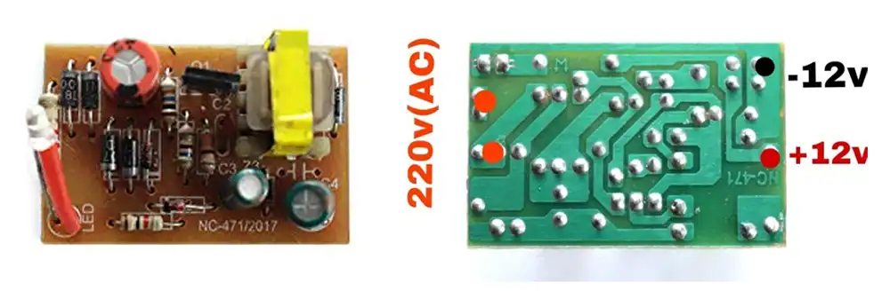
The timer module works on a wide range of DC voltage from 6V to 30V, but for safe and durable operation 6V to 12V is recommended. Here, a 220V ac to 12V dc SMPS power supply module has been used to supply the timer. Any power supply module of old 12V dc adapter can also be used. Current rating should be at least 750 mA but 1A is preferable.
Bill of Materials
| Sl. No. | Component | Quantity |
| 1 | Digital Timer Module | 1 |
| 2 | 220v ac to 6v dc SMPS module | 1 |
| 3 | 4×4 inch Plastic Casing | 1 |
| 4 | Push-to-ON Reset Switch | 1 |
| 5 | 5A Plug Socket | 1 |
| 6 | 5A Piano Switch | 1 |
| 7 | Connecting Wires | As required |
| 8 | AC Input Cable with Plug | 1 |
Circuit Diagram and Working Principle
The system can be divided into two major sections: the power supply and the timer. The power supply is a ready-made 220V AC to 12V DC module, which is easily available in the market. 220V AC supply is given through a 5A piano-type switch (S1), which acts as the main switch for the Timer and plug point where the load will be connected. The power supply module has an in-built LED indicator which indicates the availability of 12V output voltage. That 12V DC supply is fed to the timer through the input terminals of the Timer module. The same DC supply is connected to the positive of the trigger point through a push-to-on Reset switch (S2). The negative of the power supply is directly connected to the negative of the trigger point.
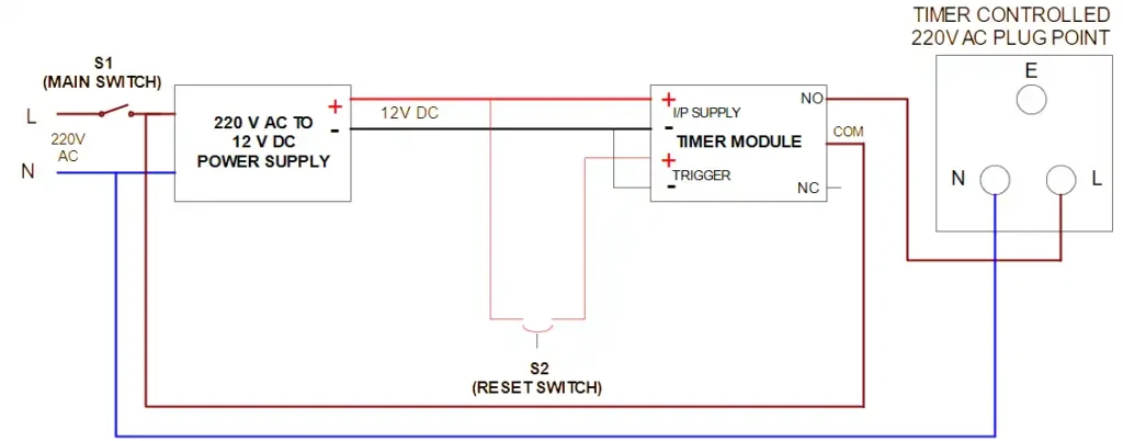
The AC main input is connected to the system through the piano switch S1, which acts as the main power control.
- The live line passes through the digital timer relay output.
- The neutral line is directly connected to the socket.
- The relay inside the timer module controls whether power flows to the socket.
- The reset switch is connected to the timer module to restart timing.
Safety Note: Ensure proper insulation and secure connections while handling AC mains.
The heart of the circuit is the digital timer module HCW-M421, which controls the ON/OFF duration of the output power.
- When the device is powered ON using the piano switch S1, the timer gets ready for a countdown.
- When the Reset switch is pressed momentarily, the timer starts counting down and the relay gets energised.
- The energised relay provides a 220V AC supply to the 220V plug point. Load like a mobile charger, a laptop charger or a pump, or anything which is intended to be controlled, is to be connected to this plug. That load gets power through the relay. The connected appliance (e.g., mobile charger) receives power through the timer-controlled output.
- When the countdown is finished, the relay gets de-energised, and the power supply to the plug gets cut off. For a phone or laptop, the preset time may be set as 120 min to 150 depending upon the battery charging time. For a water pump for an overhead tank the time can be set to 10-15 min depending on the requirement.
- The push-to-ON reset switch (S2) can be used to restart the timer cycle whenever needed
Note: It may be noted that, the maximum load can be connected safely as high as 500-550 watts (2-2.5A at 220V) as a high load may damage the contact of the relay of the timer module. If a higher load is intended to be controlled, a 220V Contactor Coil may be used. In that case coil of the Contactor will be operated through the timer relay, and load will be connected to the power terminals of the contactor.
Programming of the Digital Timer module
As it has been mentioned earlier, the digital timer module has versatile timer functions and we are using only one mode where the load will be cut after elapsing the set time. But the timer has 4 primary timing Programs (P1, P-2, P3 and P-4) with some sub categories under P1 and P3 namely P1.1, P1.2, P1.3 and P3.1 & P3.2. P-1 is a simple program to switch off a load after a preset time. But there are some small variations under it. In P1.1, while the countdown is in progress, we cannot change the timing by pressing the Reset button, but in program P1.2, if we press the Reset button while the countdown is in progress, it changes the time from the initial stage. For example, with program P1.2, if we set the time for 10 sec after which the load will be off, but say after counting of 7 sec, if we press the reset button the counting will again start for 10 sec. But in program P1.1, pressing the Reset switch will not affect the countdown. It will be a big article if we discuss all the program modes. So we are limiting our discussion on the particular mode of P1.2, which we are using to make the off timer.
Selection of Mode and Delay Time after which the timer should cut off the power supply of the 220V AC plug point (program mode P1.2) is done by pressing 4 buttons of the timer module as per the following sequence:
- Put on the main power switch (S1) and the power of Timer.
- Press SET button for 3 sec, it will show the timer mode.
- Press UP /DN button to select the particular mode of P1.1. It will sequentially show P1.1, P1.2, P1.3, P-2, P3.1, P3.2 and P-4.
- After selection of mode P1.2, press the SET button for 1 sec. to finalise/set the Mode P1.2.
- Then it will show OP, which means setting the operation time i.e. for how much time we want to set the timer. We can set the time ranging from 0.1 sec to 999 sec.
- Now observe where the dot point is in the 3-digit seven-segment display. If dot is at the extreme right, then the unit is second. Now press the STOP button once, the dot will be shifted to the 2nd digit, which means the first 2 digits will show seconds but 3rd digit will show 10th of a second. Then press the STOP button again, all 3 dots will be visible. This means the unit is in minutes and now we can select the time in minutes.
- Then press UP button to increase the time or DN button to decrease the time. Set the desired time in minutes (in our case it should be 120 to 150 min for mobile charging)
- Now press the SET button for 3 seconds. This will save the setting of program P1.2 with the desired time of say 120 min.
- Now our timer is ready.
- As soon as we will press the RESET button (S2), the countdown will start from set value of 120 min. The plug will get power through an energised relay. After elapsing the set time, the display will show 000 and plug will be off as relay will get de-energised.
Construction
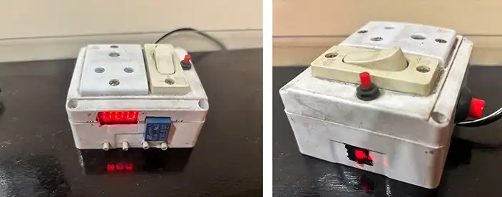
- Take a 4×4 inch plastic casing and mark positions for:
- Timer module display
- Plug socket
- Piano switch
- Reset button
- Push rods for pressing the on board switches of timer module PCB
- Cut openings carefully using a cutter or drill.
- Mount all components securely:
- Fix the timer module inside
- Install socket and switches on the front panel
- Place 4 plastic push rods (dia. 3-4mm)to operate the micro switches of timer
- Complete wiring as per the circuit:
- Use insulated wires
- Ensure tight connections
- Close the casing and test the setup.
Operation
- Plug the device into a wall outlet.
- Set the desired time on the digital timer module.
- Connect the mobile charger or appliance to the socket.
- Turn ON the piano switch.
- Press the Reset switch to start the countdown of the timer and power on the plug socket
- The plug will automatically get switched OFF after elapsing the preset time.
To reuse, press the reset switch again.
Applications
- Mobile phone charging control
- Laptop charger cut-off
- Electric kettle or iron timer
- Pump control
- Battery charging systems
- Energy-saving automation
Advantages
- Prevents overcharging damage
- Reduces standby power consumption
- Easy to build and maintain
- Affordable compared to commercial timer plugs
Limitations
- Suitable only for low-power devices (within 5A rating)
- In case of a higher load to be controlled, necessary modification using a Contactor is required as mentioned earlier.
- Requires careful handling of AC mains
- Limited to preset timer functionality
- Max delay time is 999 minutes
Video Tutorial
Conclusion
This DIY Smart Timer Plug is a practical and useful project for everyday life. It combines simplicity with functionality and helps conserve energy while protecting your devices. With minimal components and basic wiring skills, anyone can build this compact automation device at home.
About Author: Dr. Gautam Kumar Mandal, PhD, General Manager and Head of Industrial Engineering Department, Steel Authority of India Limited (SAIL), Durgapur Steel Plant
- An electronics enthusiast with three patents for innovations
- Contributed several articles in International Journals
- Published various DIY articles in EFY
- Implemented many Innovation projects in the Integrated Steel Plant, on home automation and Roof Garden automation
- Recipient of the SAIL Corporate Award for Excellence under the category of “R&D and Innovation Expert” for 2023