


 Earlier, we made a futuristic wireless tile called Smart PowerTile that allowed home walls to wirelessly power electronic/electric devices, similar to a MagSafe. With this, a Raspberry Pi placed on a wall could be powered wirelessly.
Proceeding with that concept, you will today learn to design a wireless power case for the Raspberry Pi that will further enable you to design a smart wireless IoT device for use with the Smart PowerTile. In case you don’t have a Smart PowerTile, you can still power your IoT device using the power case with any wireless power adaptor.
With that said, let’s begin designing the powercase for the RPi.


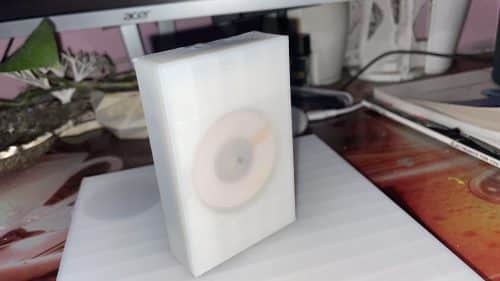
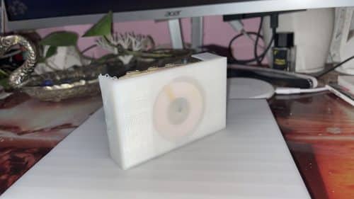
For the wireless power case of a Raspberry Pi/ IoT device, place the electronics components along with the 3D printed power case layers. Three plastic layers cover the body of the power case. For this, I chose the PLA plastic filament.
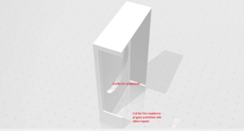
The bottom layer will have a cavity that is the size of a wireless power copper wire loop. The magnetic core for the MagSafe system in the cavity must have a thin layer so that the electromagnetic field can easily penetrate it and complete mutual induction with the PowerTile or any other wireless power transmitter.

The bottom of the cavity must be thin enough for mutual induction to occur with the two coils. The magnetic field should penetrate the plastic layer, which must be strong to hold the copper wire and withstand the attractive forces present between the magnets used in the MagSafe.
Also, the layer should be thick enough for the 3D printer to print it, that is, the printing material’s thickness should be greater than the 3D printer’s nozzle thickness. So if you wish to print a layer 0.1mm thick from a 3D printer whose nozzle thickness is 0.5mm, then the process won’t be possible.
After several trials and errors, I figured out the perfect thickness for the cavity bottom layer to be from 0.2mm to 0.28mm. Make sure to cut slots in the power case for various USB ports, and other inputs and outputs.
Next, export the 3D design case and 3D print it.
Then, insert electronic components inside the power case including the power receiving coil and its circuitry. For MagSafe, place the magnet in the centre of the cavity so that an IoT device can easily stick to the PowerTile.
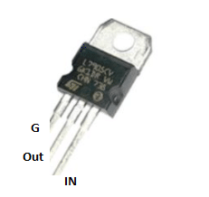
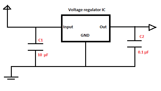
Next, add a voltage regulator for the RPi, which may vary with the type of IoT device used. Here, our device needs 2A, 5V regulated power. Therefore, include a 2A, 5V voltage regulator LM7905 IC. Connect its output to the Raspberry Pi power pin i.e. 5V pin and the GND pin to GND pin of the RPi.
After soldering the components, place the copper coil circuits and the MagSafe magnet in the cavity, and glue them. 
Next, put another layer of PLA 3D printed material of case cavity size and fix the Raspberry Pi over it. After that, you can put the device on the PowerTile.
The magnetic MagSafe system auto aligns the power coil at the centre and helps the IoT device stick to the PowerTile, enabling the Raspberry Pi to start working without connecting to an adaptor – like magic.
Congrats !! You have finally designed the power case for a wireless-powered device.
The series will continue with more wireless powering technology versions.