With booming solar industry there is a need for measurement instruments to test the various components of solar-powered systems
COL (RETD) N.C. PANDE
 JULY 2011: Solar energy has been harnessed by humans since ancient times using a wide range of ever-evolving technologies. The growing environmental concerns and demand for alternatives to fossil fuel-based energy sources have increased interest in solar cells as a long-term, exhaustless, environment-friendly and reliable energy technology. Continuous efforts to develop various types of solar cells are being made in order to produce solar cells with improved efficiencies at a lower cost, thereby taking advantage of the vast amounts of free energy available from the sun. Solar technology is being used in residential, commercial and military applications including space heating and cooling through solar architecture, potable water via distillation and disinfection, daylighting, solar hot water, solar cooking, and high-temperature process-heat for industrial purposes.
There has been an explosive growth in the solar industry, which in turn has intensified the need for measurement solutions for testing of various components of solar powered systems. Measurement solutions come in two main forms—complete turn-key solutions and test-system building blocks that must be fitted together and wrapped in software. They cater to the requirements during research and development, manufacturing processes, deployment of the system on ground and finally maintenance of the system.
The major component in solar energy-based systems is a solar or photovoltaic (PV) cell. It is a solid-state device, basically a p-n junction with a very large light-sensitive area that converts the light energy directly into electricity by the photovoltaic effect. To increase their utility, dozens of individual PV cells are interconnected in a sealed, weather-proof package called a module. To achieve the desired voltage and current, modules are wired in series and parallel in a PV array, or what is called a solar panel. The flexibility of the modular PV system allows designers to create solar power systems that can meet a wide variety of electrical needs. PV cells can be modeled as a current source in parallel with a diode. When there is no light present to generate any current, the PV cell behaves like a diode. As the intensity of incident light increases, current is generated by the PV cell.
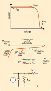
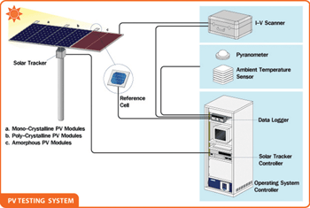
Most solar cell parameters can be obtained from simple I-V measurements. I-V testing systems include the light source, measurement electronics, computer and software needed to measure solar cell’s I-V curves (refer figure on next page). The solar simulator illuminates the test device while the electronic load sweeps the cell voltage from a reverse-bias condition through the power quadrant, and beyond the open circuit voltage (Voc). The system’s computer gathers data, calculates solar cell parameters, generates printable test reports, and saves test data in text files. Solar cells are characterised by a maximum Voc at zero output-current, and a short circuit current (Isc) at zero output-voltage.

Solar cell 1-V curves and equivalent circuit (Courtesy: Agilent Technoligies)
Testing of the solar cell is required for research, quality assurance and production. PV cell testing is an important part of PV semiconductor design and fabrication, and includes a variety of tests that help ensure the quality and efficiency of the product.
Although the measurement accuracies, speeds and other parameters may differ across different levels, there are a number of key parameters that are typically measured in any testing environment. Two simple tests can be performed to obtain all of the necessary data for solar cell I-V characterisation—the forward-bias (illuminated) test and the reverse-bias (dark) test.
Parameters of solar cell and module for measurement
Voltage at maximum power (Vmp). It is the highest voltage the panel can produce while connected to a system and operating at peak efficiency.
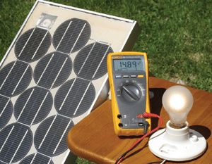
Open circuit voltage (Voc). It is the maximum voltage that the panel can produce when not connected to an electrical circuit or system, that is, when the current through the solar cell is zero. It is the maximum voltage available from the solar cell. Voc can be measured with a meter directly contacting the panel’s terminals or the ends of its built-in cables.
Short circuit current (Isc). It is the current through the solar cell when the voltage across the solar cell is zero.
Maximum power current (Imp). It is the maximum current available when the panel is operating at peak efficiency in a circuit.
Maximum power point (Pmax). It is the condition under which the solar cell generates its maximum power. The current and voltage in this condition are defined as Imax and Vmax , respectively.
Fill factor (FF) and the conversion efficiency (η). These are metrics used to characterise the performance of the solar cell. Fill factor is defined as the ratio of Pmax divided by the product of Voc and Isc.
Conversion efficiency. It is the percentage of power converted (from absorbed light to electrical energy) and collected when a solar cell is connected to an electrical circuit. It is the ratio of Pmax to the product of the input light irradiance (E) and the solar cell surface area (Ac).

Internal resistances of a solar cell. RS and RSH are internal parasitic series and shunt resistances, respectively. During operation, the efficiency of solar cells is reduced by the dissipation of power in these resistances.
Series resistance in a solar cell has three causes: first, the movement of current through the emitter and base of the solar cell; second, the contact resistance between the metal contact and the silicon; and finally the resistance of the top and rear metal contacts. The main impact of series resistance is to reduce the fill factor. Although excessively high values may also reduce the short circuit current. RSH for an ideal cell would be infinite and would not provide an alternate path for current to flow, while RS would be zero, resulting in no further voltage drop before the load. Decreasing RSH and increasing RS will decrease the FF and PMAX.
Capacitance measurement. This includes the measurement of parallel capacitance (Cp), carrier density (Nc) and drive-level density (Ndl).
Time domain measurement. Minority carrier lifetime (τ), surface recombination velocity (S) and minority carrier diffusion length (Ld) are measured under this category.
Dark I-V solar cell testing
Highly accurate characterisation of solar cell’s resistance and diode properties are measured by this test. By blocking all light, the PV cell can be tested as a passive diode element to determine its breakdown diode properties and internal resistances. This type of testing is performed to ensure that the quality of the cell meets the application’s criteria and the cell is defect-free.


