


Build, test and see how circuits work, analog, digital or RF, without paying anything. Find out how this free tool can make electronics easy and fun.
QUCS (Quite Universal Circuit Simulator) is a free, open-source tool for simulating electronic circuits. It offers a graphical interface to design schematics and analyze circuit behavior for analog, digital, RF, and microwave designs. QUCS supports DC, AC, S-parameter, and digital simulations with VHDL/Verilog. You can use it to test circuits before building physical prototypes, saving time and cost. It is also recognized for being more user-friendly than many other circuit simulators. “It is easy to use, intuitive, and provides a clear graphical interface for drawing schematics and viewing results,” added one user.

QUCS originally consisted of a simulator called Qucsator and a GUI for schematic design and plotting. Its workflow and focus on RF design were inspired by commercial tools of its time. Later, QUCS added support for other simulators, including VHDL, Verilog, and some SPICE engines, though Qucsator itself has never been SPICE-based, nor was it ever replaced by a SPICE engine.
Today, it provides a library of analog and digital components, including sub-circuits compatible with multiple simulators. It is designed to be simpler to use than other tools like gEDA or PSPICE. The current development roadmap focuses on separating schematic representation, device modeling, and simulator choice, following principles from the IEEE1364 standard.
The name QUCS represents a family of free electronic circuit simulators, including Qucs Original, Qucs-S, and QucsStudio. All versions feature a powerful, user-friendly graphical interface that is often considered better designed than many paid tools. This makes QUCS appealing to both hobbyists and professional engineers. The software is available on a wide range of operating systems, including GNU/Linux, Windows, FreeBSD, macOS, NetBSD, and Solaris. “A capable simulation tool available at no cost, offering an alternative to paid EDA software,” said an user.
QUCS and Variants
1. Original QUCS: Its goal was to become a complete electronic circuit simulator, supporting standard SPICE-style simulations (DC, AC, transient) as well as RF-focused simulations like S-parameters and Harmonic Balance. Two key features set QUCS apart:
- Qucsator Simulation Engine: A unique simulation engine separate from SPICE.
- Graphical Interface: A Qt-based GUI that provides an intuitive and efficient user experience.
2. Qucs-S: Qucs-S, also called QUCS with SPICE, builds on the original QUCS by adding support for SPICE-based engines such as Ngspice, XYCE, and SpiceOPus, in addition to Qucsator. Qucs-S allows users to combine the familiar Qucs interface with widely used SPICE simulation capabilities.
3. QucsStudio: QucsStudio is an independently developed evolution of the original Qucs project. It introduces a new simulation engine and unique capabilities not found in other variants, including:
- System-level simulation
- Electromagnetic simulation of PCBs
- Integration with C/C++, Octave, and KiCad
QucsStudio is the most ambitious of the three, offering extensive possibilities for professional use, particularly in smaller environments. It supports a wide range of projects, simulations, and co-simulations, making it the most versatile version of the QUCS ecosystem.
What does it offer to its users?
QUCS offers engineers and hobbyists a versatile platform for both analog and digital circuit design. “Well suited for learning electronics, with basic components and tutorials that support simple circuit examples,” said another user. Its range of tools makes it suitable for RF, microwave, and general-purpose simulations, while also supporting optimization and integration with other CAD/EDA tools.
- Circuit Simulation: Perform DC, AC, S-parameter, harmonic balance, and transient analysis.
- Component Library: Access a wide range of components, including resistors, capacitors, diodes, MOSFETs, HICUM and BSIM transistors, and operational amplifiers.
- RF and Microwave Design: Tools for transmission line calculations, filter synthesis, and attenuator design.
- Visualization & Post-Processing: Advanced plotting options (3D Cartesian, polar, Smith charts) and built-in equation solvers for data analysis.
- Integrated Workflow: GUI supports schematic entry, simulation, and result visualization; compatible with other CAD/EDA tools for netlist and dataset import/export.
- Digital Simulation: Supports VHDL and Verilog for logic circuits.
- Optimization: Circuit performance can be optimized using tools like ASCO.
For users seeking specialized functionality or enhanced workflow, Qucs offers two main forks: Qucs-S, which integrates SPICE-based simulation engines like Ngspice or Xyce, and QucsStudio, an advanced fork with improved GUI, PCB support, and system-level simulation. Together, these features make Qucs a flexible and powerful environment for both learning and professional circuit design.
Latest Update
The latest stable release of the original QUCS was version 0.0.19, launched on January 22, 2017. However, development has largely shifted to forks such as Qucs-S, which released version 25.2.0 on September 6, 2025, and QucsStudio, which released its uSimmics version 5.9 on January 10, 2026, showing that related projects continue to be actively developed. As of 2026, the features of the QUCS ecosystem vary by branch or fork:
1. QucsStudio (v5.9, Jan 10, 2026) – the most feature-rich variant (often called uSimmics):
- System Simulation: High-level simulation of communication systems using complex envelopes.
- Electromagnetic (EM) Field Simulator: Analyzes microstrip-based designs with finite-difference time-domain methods.
- Antenna Analysis: Tools within the EM simulator for antenna design and characterization.
- Arbitrary Transmission Lines: Supports diverse line types, including slotlines and waveguides.
- Integrated Scripting: Native C/C++ and Octave support for post-processing and custom model creation.
2. Qucs-S (v25.2.0, Sep 6, 2025) – the most active open-source fork, focused on SPICE integration:
- Expanded Backend Support: Native integration with Ngspice (v45+), Xyce, and SpiceOpus.
- Microstrip Simulation for Ngspice: Newly added microstrip line support within Ngspice.
- Advanced Magnetic Modeling: Jiles-Atherton core models and a dedicated magnetic cores device group.
- Modern Rendering Engine: Redesigned schematic rendering with support for wires at arbitrary angles.
- New Component Libraries: Expanded libraries for VDMOS devices and ferrite cores (Amidon, Epcos, Ferroxcube).
3. QUCS Original (v0.0.19) – the legacy stable version:
- Core Simulation Types: DC, AC, S-parameter, Transient, and Noise analysis.
- Digital Simulation: VHDL and Verilog-HDL support for logic circuits.
- Legacy Toolset: Transmission line calculator, filter synthesis tool, and attenuator design tool.
What does the free version have for users?
| Simulation Capabilities | • Circuit Types: Supports analog, digital, mixed-signal, and RF designs. • Analysis Types: Perform DC, AC, Transient, Harmonic Balance, Noise, and S-parameter analysis. • Digital Simulation: Works with VHDL or Verilog, often via FreeHDL or Icarus-Verilog. • Circuit Optimization: Enables minimization of cost functions using external tools like ASCO. |
| Component Library & Modeling | • Extensive Library: Includes resistors, capacitors, inductors, diodes, transistors (JFET, MOSFET, MESFET), and OpAmps. • Model Support: Compatible with transistor models like HICUM and BSIM (3.34, 4.30). • File Import/Export: Supports netlists, datasets, and Touchstone files (S-parameter datasets) from other CAD/EDA tools. |
| Graphical Interface & Data Visualization | • Schematic Capture: User-friendly GUI for drawing circuits. • Data Visualization: View results in Smith charts, Cartesian, Tabular, Polar, 3D-Cartesian, and Truth Tables. • Post-Processing: Built-in equation solver for calculations like power or efficiency. |
| Built-in Tools & Utilities | • Synthesis Tools: Filter synthesis, transmission line calculations, and attenuator design. • Text Editor: Integrated editor for netlists and log viewing. |
| Licensing & Availability | • Free & Open Source: Released under GNU GPL. • Cross-Platform: Runs on Linux, Windows, macOS, and BSD systems. |
Getting started
To start using the QUCS, you need to install the software, understand the interface, create a circuit, run a simulation, and check the results.
1. Installation: Before building circuits, QUCS must be installed on the system. The software is available for Windows, Linux, and macOS.
On Windows, QUCS is provided as an installer or a portable ZIP file. You can download the software from the download page or can get the portable zip file from the Github. The installer sets up the simulator and requires libraries automatically. The portable version can be run without installation.
On Linux, QUCS is available through package managers and prebuilt packages.
- Debian / Ubuntu (APT install): sudo apt-get install qucs
- FFor Other Linux distributions (.deb, .rpm, AppImage), click here.
On macOS, QUCS can be installed using MacPorts. Click here for the installation guide. You can also used QUCS install command(sudo port install qucs).
QUCS-S is an extended version that works with SPICE engines like Ngspice and Xyce. Click here for the installation guide. This version is useful for more accurate and advanced simulations.
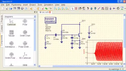
2. User Interface Theory: After launching QUCS, the interface is divided into functional areas:
- Main Window: Used to draw schematics and view waveforms or tables.
- Left Sidebar: Contains project manager, component libraries (resistors, sources, digital blocks), and simulation blocks.
- Toolbar: Used for wiring, labeling nodes, running simulations, and saving designs.
This layout follows a schematic-first workflow, similar to other EDA tools.
3. Circuit Building Theory: Circuit building in QUCS involves placing components, wiring them into a schematic, assigning values, and adding a simulation block that defines how the circuit will be analyzed (DC, AC, or transient) based on circuit equations.
4. Simulation Theory and Running the Simulation: When the Simulate button is clicked, QUCS converts the schematic into a netlist, solves the circuit equations, and stores the results as datasets. To run the simulation, click Simulate or press F2, and a data display window will open automatically.
5. Results and Data Display Theory: QUCS does not show results directly on the schematic. Results are viewed in a data display window.
- Tabular View: Shows numeric values (voltages, currents)
- Cartesian Plots: Shows graphs over time or frequency