Light fidelity (Li-Fi) is a widely adopted form of wireless communication that uses optical energy to verify device functionality. A key challenge lies in establishing communication between two heterogeneous devices over extended distances, especially under full daylight conditions.
To capture the laser module’s intermittent light transmission on video, the BITDELAY is intentionally set to 10ms. For data transmission, however, a 2-3ms BITDELAY has been tested and proven effective. Reducing it to 1ms leads to errors and the loss of alphanumeric characters.
POC Video Tutorial
The system has been validated to sustain reliable communication across a 152cm (60-inch) distance between the transmitter (Tx) and receiver (Rx) modules, even in bright lighting.

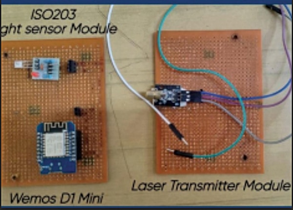
Table of Contents
The setup confirms the viability of using different microcontrollers—for instance, an ESP8266-based WeMos D1 Mini at the transmitter end and another ESP8266 module at the receiver end. To introduce heterogeneity, other combinations such as ESP8266 with Arduino, ESP32 with ESP8266, nRF with ESP8266, or STM32 with Arduino may also be employed.
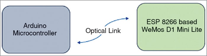
Fig. 1 displays the authors’ prototype through key visuals, while Fig. 2 outlines the system’s block diagram. The components used are listed in the Bill of Materials Table 1.
| Table 1: Bill of Materials | ||
| Components | Description | Quantity |
| WeMos D1 Mini | For programming of Rx | 1 |
| WeMos D1 Mini | For programming of Tx | 1 |
| ISO 203 Rx Module | To receive the data bit sequence | 1 |
| Laser Tx module | To transmit the data bit sequence | 1 |
| Jumper wires | Male-female jumper wires to connect | As required |
Li-Fi Transmitter and Receiver Circuit and Working
The circuit is relatively simple. Fig. 3 shows the combined circuit diagram of transmitter and receiver based on WeMos D1 Mini. On the left side is the receiver circuit, and on the right side is the transmitter circuit with the laser diode (see Fig. 3). Refer to Table 2 for board label specifications and pin functions of the microcontrollers.