


I built a Raspberry Pi FM transmitter using only software without any external RF modules or transmitter HATs. Let me explain step-by-step.
The Raspberry Pi, a versatile single-board computer, can be transformed into a functional FM transmitter without the need for any separate transmitter HAT or additional hardware. This is achieved by leveraging the Pi’s built-in peripherals, such as the general clock output or PWM (Pulse Width Modulation) generator, to produce VHF (Very High Frequency) signals in the FM radio band (typically 87.5–108 MHz).
By programming the GPIO pins to output a modulated signal, the Pi can generate frequency-modulated waves that carry audio data, effectively acting as a low-power FM broadcaster. A simple wire attached to a specific GPIO pin serves as an antenna to radiate the signal over short distances.
This capability stems from early projects like PiFM, which demonstrated how to use the Pi’s clock signals for FM transmission. Over time, FM transmitter projects were adapted to use DMA (Direct Memory Access) for more efficient data handling, reducing CPU load and improving stability. These were later enhanced with RDS (Radio Data System) capabilities, allowing the transmission of metadata like station names, song titles, and time information alongside the audio.
For instance, PiFmRds utilizes the Raspberry Pi’s PWM generator for VHF signal generation and includes RDS support. The project discussed in this article is based on the fm_transmitter repository, a simple and effective implementation that focuses on basic FM audio transmission using the clock output, without native RDS. For RDS features, users can explore enhanced variants like PiFmRds.
This setup is ideal for educational purposes, experimentation, or short-range broadcasting (e.g., in a car or home setup), but note that transmitting on FM frequencies may require licenses in many countries and could be illegal without proper authorization.
Table of Contents
Bill Of Materials
| Components | Quantity |
| Raspberry Pi ( Any version ) | 1 |
| USB Mic | 1 |
| 5V 2A Adapter | 1 |
| Long Wire | 1 Meter |
| Female Header | 1 |
The design of the Raspberry Pi FM transmitter revolves around using the Pi’s hardware capabilities to generate and modulate radio signals directly from software. Here’s a breakdown of the key components and principles:
Raspberry Pi FM Transmitter Hardware Design
The hardware design of the Raspberry Pi FM transmitter is elegantly minimal, relying entirely on the Raspberry Pi’s built-in capabilities to generate and transmit FM radio signals without requiring additional transmitter modules or specialized hardware.
At its core, the system uses the Raspberry Pi’s general clock output on GPIO4 (Pin 7 on the GPIO header) to produce a high-frequency carrier wave in the FM band, typically between 87.5 and 108 MHz.
By rapidly toggling this pin, the Pi generates a square wave that, when modulated with audio data, creates a frequency-modulated (FM) signal suitable for broadcasting.
A simple 20-40 cm wire, such as a jumper wire or insulated copper strand, is connected to GPIO4 to serve as a quarter-wave antenna, radiating the low-power signal (approximately 10-50 mW) over a short range of a few meters to tens of meters, depending on environmental factors and frequency settings.
For Raspberry Pi 4 users, GPIO21 (Pin 40) can be used as an alternative to mitigate potential interference from Wi-Fi or Bluetooth modules, which may disrupt higher-frequency transmissions.
No external amplification or RF circuitry is needed, as the Pi’s programmable peripherals handle signal generation directly. This approach leverages the Pi’s clock or PWM (Pulse Width Modulation) capabilities, where the square wave output is naturally filtered by the air and the receiver’s circuitry to approximate the sine waves required for FM reception.
The design’s simplicity eliminates the need for components like dedicated RF chips (e.g., Si4713), making it an accessible and cost-effective solution for hobbyists experimenting with software-defined radio.
Configuration and Installation
The software uses DMA to transfer audio data to the GPIO for modulation, reducing CPU load. It supports customizable frequency (-f), bandwidth (-b), looping (-r), and input from files or stdin. No native RDS in this repo; for RDS, use PiFmRds.
Update system:
sudo apt-get update
sudo apt-get upgrade
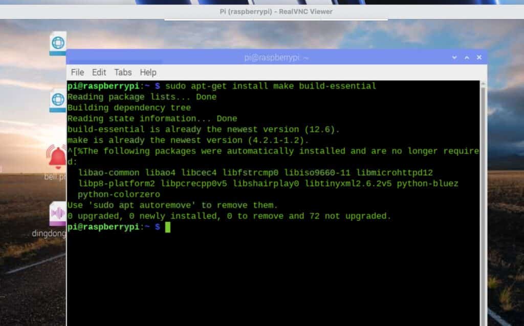
Install dependencies:
sudo apt-get install make build-essential
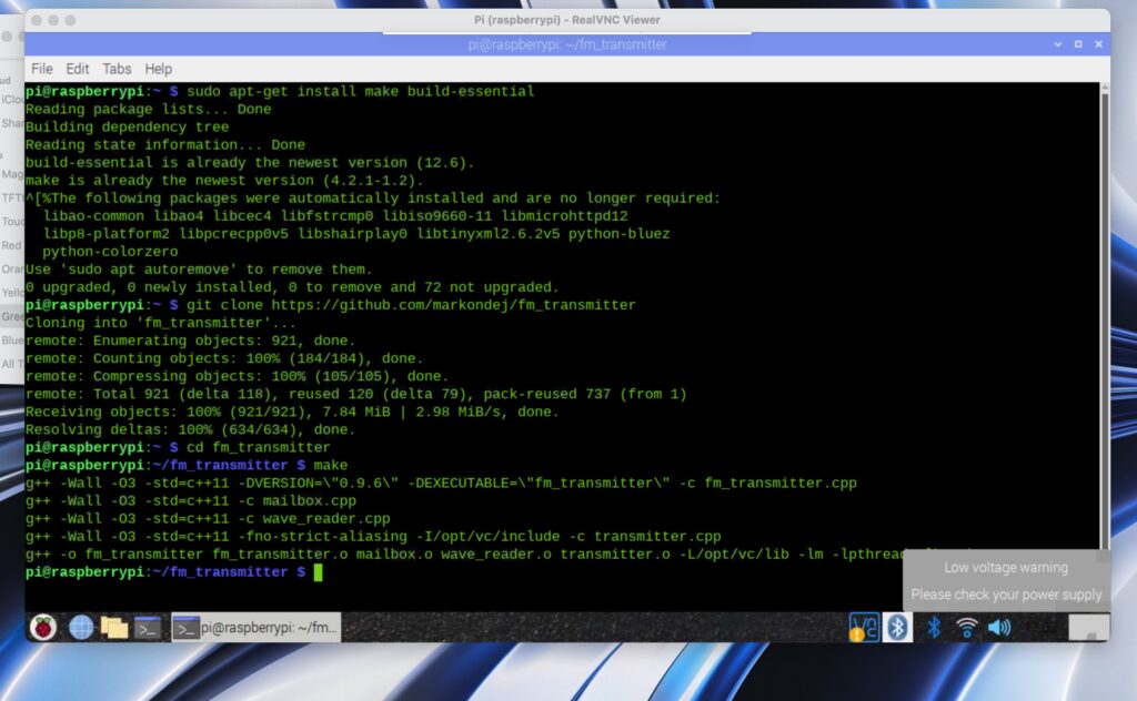
Clone and compile:
git clone https://github.com/markondej/fm_transmitter
cd fm_transmitter
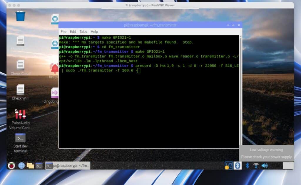
make GPIO21=1
For audio conversion (optional):
sudo apt-get install sox libsox-fmt-mp3
Commands to Use FM Transmitter via Linux Terminal
Use the compiled fm_transmitter binary from the terminal:
- Basic playback:
sudo ./fm_transmitter -f 100.0 acoustic_guitar_duet.wav
(Transmits at 100 MHz; tune radio to 100.0.)
With looping:
sudo ./fm_transmitter -f 100.0 -r acoustic_guitar_duet.wav
- Custom bandwidth:
sudo ./fm_transmitter -f 100.0 -b 150 acoustic_guitar_duet.wav - Live microphone input (requires USB mic):
arecord -D hw:1,0 -c 1 -d 0 -r 22050 -f S16_LE | sudo ./fm_transmitter -f 100.0 – - MP3 streaming:
sox example.mp3 -r 22050 -c 1 -b 16 -t wav – | sudo ./fm_transmitter -f 100.0 – - Disable DMA (CPU mode):
sudo ./fm_transmitter -f 100.0 -d 255 acoustic_guitar_duet.wav
For Pi 4 interference: Set CPU governor to powersave:
echo “powersave” | sudo tee /sys/devices/system/cpu/cpu0/cpufreq/scaling_governor
Simplifying the Process: Making a GUI for the Transmitter
To simplify usage without command-line input, create a Python GUI using tkinter. This allows selecting files, setting frequency/bandwidth, toggling loops, and starting/stopping transmission via buttons. The GUI automates commands by running fm_transmitter as a subprocess.
How the GUI Works Using Subprocess and Executing Commands Automatically
The GUI uses Python’s subprocess.Popen to execute the fm_transmitter binary with user inputs as arguments (e.g., sudo ./fm_transmitter -f 100.0 -b 100 file.wav). It builds the command list dynamically and runs it in the background. To stop, it sends a SIGTERM signal via os.kill. Validation ensures valid inputs before execution. The GUI handles errors with message boxes and updates a status label. For live input, it could pipe data, but this version focuses on file playback.
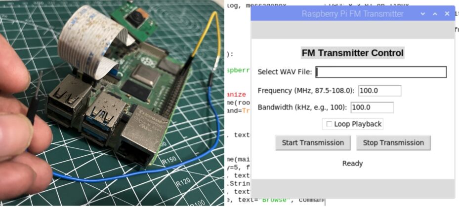
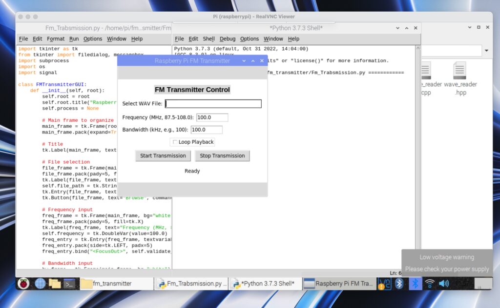
GUI Design Details: Textboxes and All UI Buttons
- Layout: Uses frames for organization, with padding for spacing. Background set to white, text to black for visibility.
- Title Label: “FM Transmitter Control” (bold, centered).
- File Selection: Label “Select WAV File:”, textbox (width 40, shows path), “Browse” button (opens file dialog for WAV files).
- Frequency Textbox: Label “Frequency (MHz, 87.5-108.0):”, textbox (default 100.0, validates on focus out/start).
- Bandwidth Textbox: Label “Bandwidth (kHz, e.g., 100):”, textbox (default 100.0, validates positive value).
- Loop Checkbox: “Loop Playback” (toggles -r flag).
- Buttons: “Start Transmission” (builds/runs command), “Stop Transmission” (kills process).
- Status Label: Displays current state (e.g., “Transmitting file at 100 MHz” or “Ready”).
First, install tkinter:
Open Linux terminal, execute the command:
sudo apt-get install python3-tk
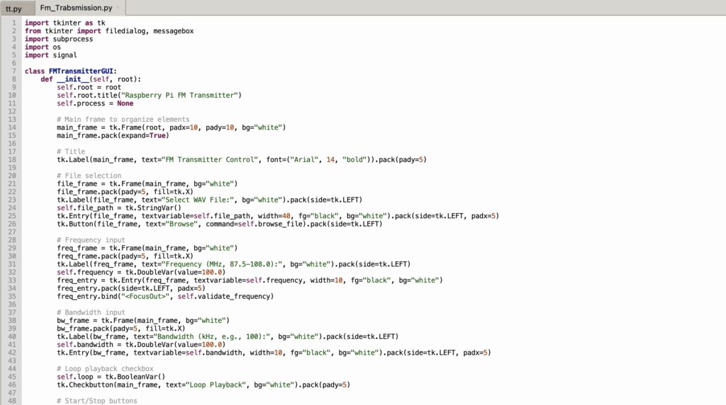
Now in code, first design the GUI and add 3 buttons, one for transmission starting and another for transmitter stop, then a text input to set frequency and a button to set that frequency, then another button to browse to select the transmission file.
Now, next Set function for each using subprocess to execute the respective function command in the lx terminal in the background as a subprocess when those buttons are clicked.
Save this code as fm_transmitter_gui.py in the fm_transmitter directory:
Recommended: Check more such tested Raspberry Pi projects.
Testing Raspberry Pi FM Transmitter
Testing the Raspberry Pi FM Transmitter involves verifying both its command-line functionality and the newly developed GUI to ensure seamless operation.
For command-line testing, begin by running a basic transmission command (e.g., sudo ./fm_transmitter -f 100.0 acoustic_guitar_duet.wav) and tune an FM radio to 100.0 MHz to confirm audio playback, checking the range of 5-20 meters depending on the environment.
Test additional features such as looping with -r, live microphone input by piping from arecord, and MP3 streaming via sox, troubleshooting any interference—especially on Pi 4—by switching to GPIO21 or adjusting the CPU governor to “powersave” mode if needed.
For GUI testing, launch the application with python3 fm_transmitter_gui.py and verify that all elements, including the frequency and bandwidth textboxes (with black text on a white background), are visible and functional. Select a WAV file using the “Browse” button, input a valid frequency (e.g., 100.0 MHz) and bandwidth (e.g., 100 kHz), toggle the “Loop Playback” checkbox if desired, and click “Start Transmission” to broadcast—confirm audio on the radio and a status update like “Transmitting file at 100 MHz.” Stop the transmission with the “Stop Transmission” button and ensure the status changes to “Transmission stopped.”
Test edge cases by entering invalid inputs (e.g., frequency below 87.5 or non-numeric values), expecting appropriate error messages, and close the window to confirm process cleanup.
For advanced use, integrating PiFmRds can be tested similarly to add RDS features, ensuring a comprehensive validation of the setup.
Related FM Transmitter projects: