The range of this FM transmitter is around 100 metres at 9V DC supply.

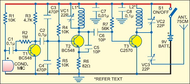
The circuit comprises three stages. The first stage is a microphone preamplifier built around BC548 transistor. The next stage is a VHF oscillator wired around another BC548. (BC series transistors are generally used in low-frequency stages. But these also work fine in RF stages as oscillator.) The third stage is a class-A tuned amplifier that boosts signals from the oscillator. Use of the additional RF amplifier increases the range of the transmitter.
Coil L1 comprises four turns of 20SWG enamelled copper wire wound to 1.5cm length of a 4mm dia. air core. Coil L2 comprises six turns of 20SWG enamelled copper wire wound on a 4mm dia. air core.

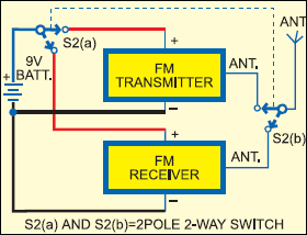
Use a 75cm long wire as the antenna. For the maximum range, use a sensitive receiver. VC1 is a frequency-adjusting trimpot. VC2 should be adjusted for the maximum range. The transmitter unit is powered by a 9V PP3 battery. It can be combined with a readily available FM receiver kit to make a walkie-talkie set as shown in Fig. 3

Related FM Transmitter Projects:


